

SFRFitCMS1
SFRFitCMS2
SFRFitCMS0
SFRFitCMS4
SFRFitCMS3
SFR-Fit-measurements
$12,400.00
This is a calibrated reference camera for Camera Monitor System (CMS) resolution (MTF) testing, designed to work with Leader SFR-Fit MTF Measurement Software (sold separately).
By using SFR-Fit Ver2.4 and a calibrated reference camera, you can measure the MTF of a CMS electronic mirror.
Includes:
- Calibrated Reference Camera
- Two types of measurement-specific hoods
- Calibration data
- Fixture for estimating the distance between display and cover glass
See also: Automotive Solutions
Description
Target imaging systems for SFR-Fit for CMS
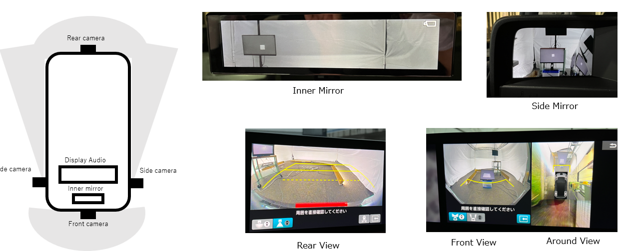
SFR-Fit for CMS can measure the MTF of various imaging systems, including rear view, around view, and electronic mirrors.
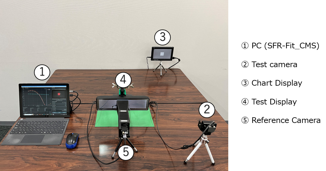
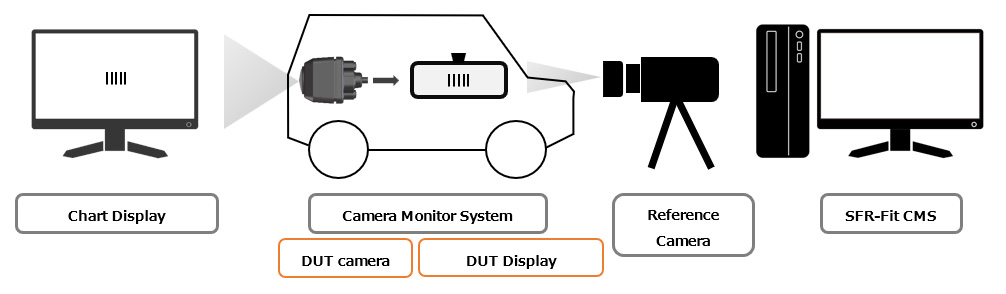
Measurement system configuration
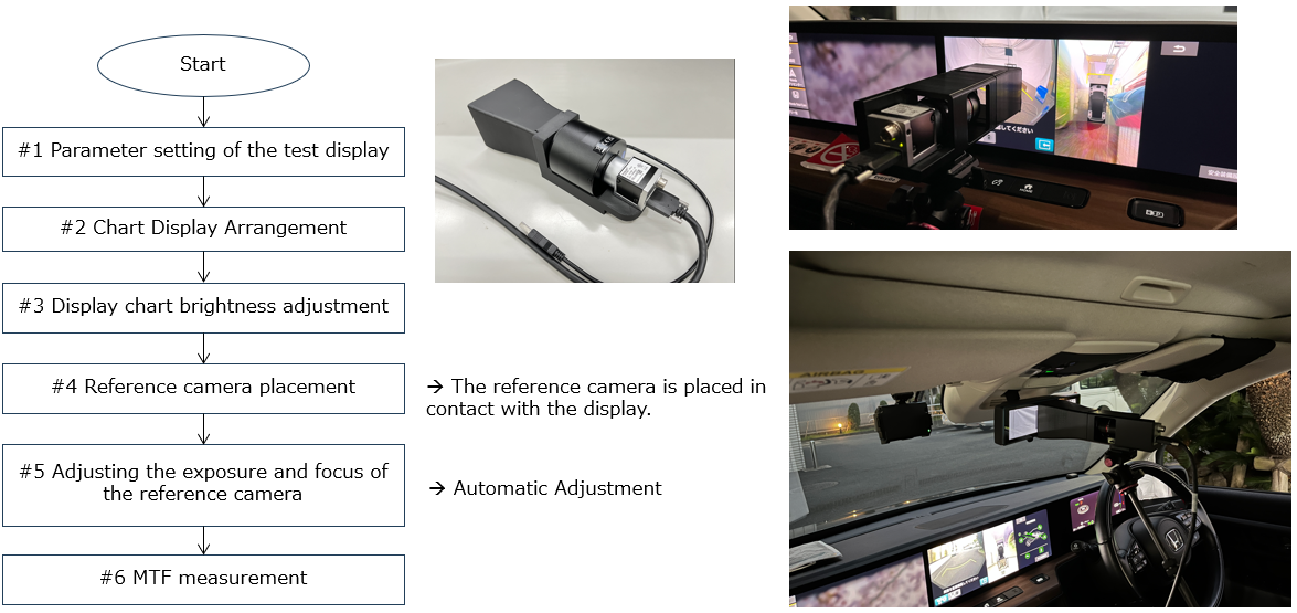
Measurement Procedure
The measurement procedure is shown below. The measurement time is about 20 minutes with one camera system (three ROIs).
Measurement example (video)
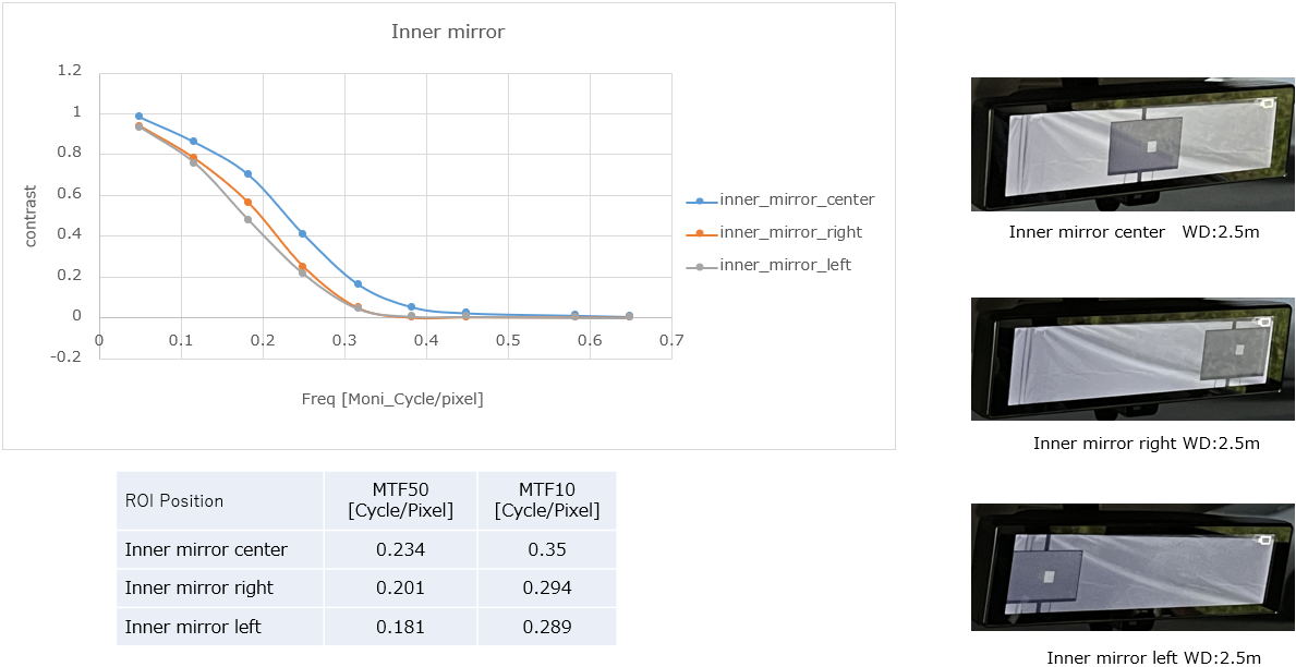
Measurement example with an electronic mirror
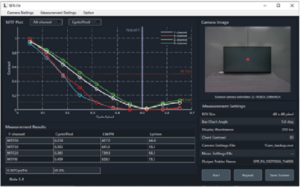
Compared to near the center, the MTF decreases in the left and right areas where the image height is high.
Technical Explanations
Measurement Algorithm
Uses the same measurement method as SFR-Fit for cameras, the only difference with the normal SFR-Fit is that the chart shown on the display is recaptured by the reference camera.
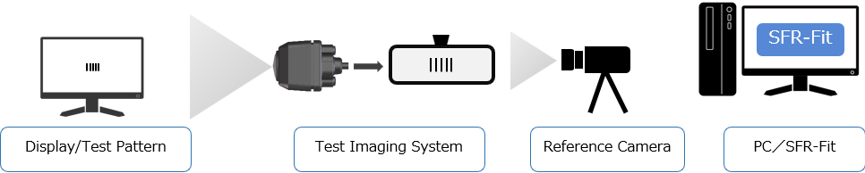
CMS measurement (total characteristics of camera +monitor)

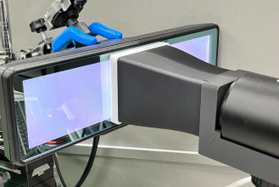
Examples of images captured with the reference camera(ROI only).
Reference Camera Specification
|
Unit |
Specification |
Remarks |
|
Lens |
f=16mm Supports 10MPixel |
Remote Control(Focus, Iris) |
|
Image Sensor |
1/1.8inch 5MPixel(2448×2048) Grayscale |
The interface is USB 3.0 |
|
Lens hood fixture |
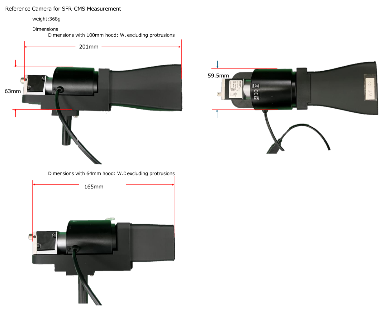
Working Distance 100mm or 64mm |
Made by Leader Electronics(3D Print) |
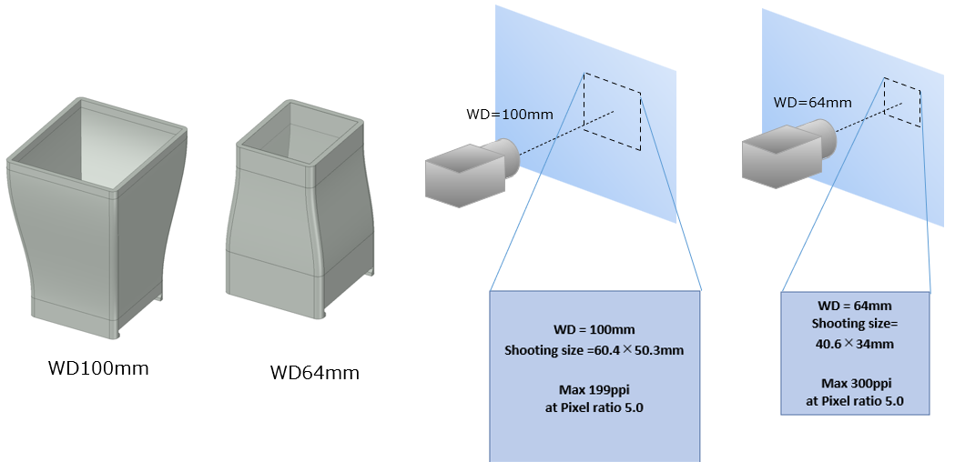
Lens Hood
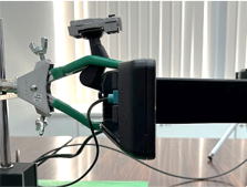
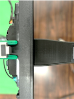
For this measurement, a lens hood is used to keep the reference camera and display in the correct position. Users need to place the lens hood tightly against the display.
|
Lens hood type |
Maximum pixel density |
|
WD100mm |
199 dpi |
|
WD64mm |
300 dpi |
Reference camera and display pixel ratio
When measuring the MTF on a display using a sine wave bar chart, it is known that if the pixel ratio is not high enough, an error in the MTF measurement can occur. This reference camera is designed to have a pixel ratio of at least 5 times.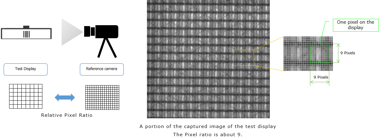
Reference camera MTF compensation
To compensate for the reduction in MTF due to the reference camera, the measurement result is divided by the MTF of the reference camera. The MTF of the reference camera is measured in advanced and isincluded with the product at the time of shipment as an MTF compensation file.
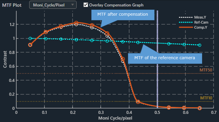
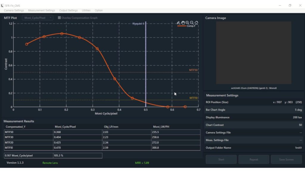
SFR-Fit CMS MTF graph
Parameters that are essential for measurement
To define the spatial frequencies on the display, users must enter the parameters of the test display.
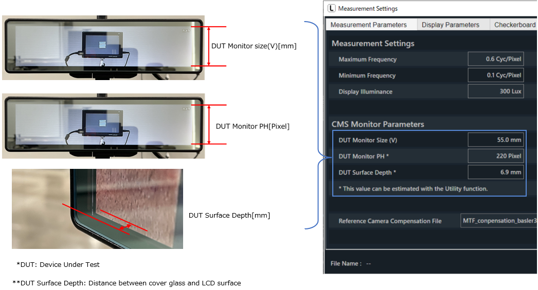
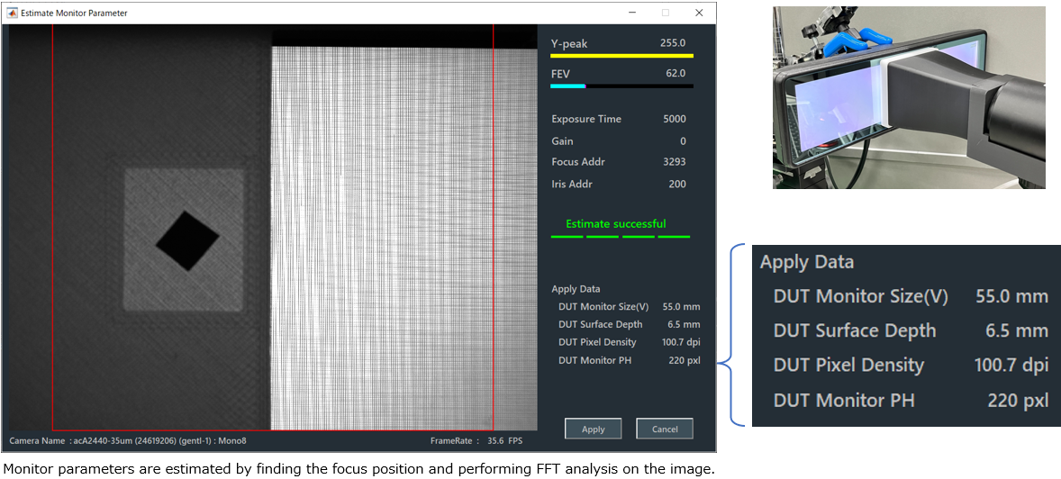
Parameter Estimation Function
Monitor PH [Pixel] and Surface Depth [mm], which are difficult to determine, can be estimated using the parameter estimation function.
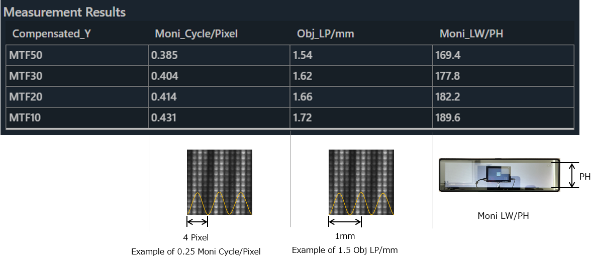
Unit of spatial frequency
SFR-Fit CMS can express the spatial frequency on the display surface from the set display specifications and shooting magnification. These units are useful for knowing the performance balance between the camera and the display.
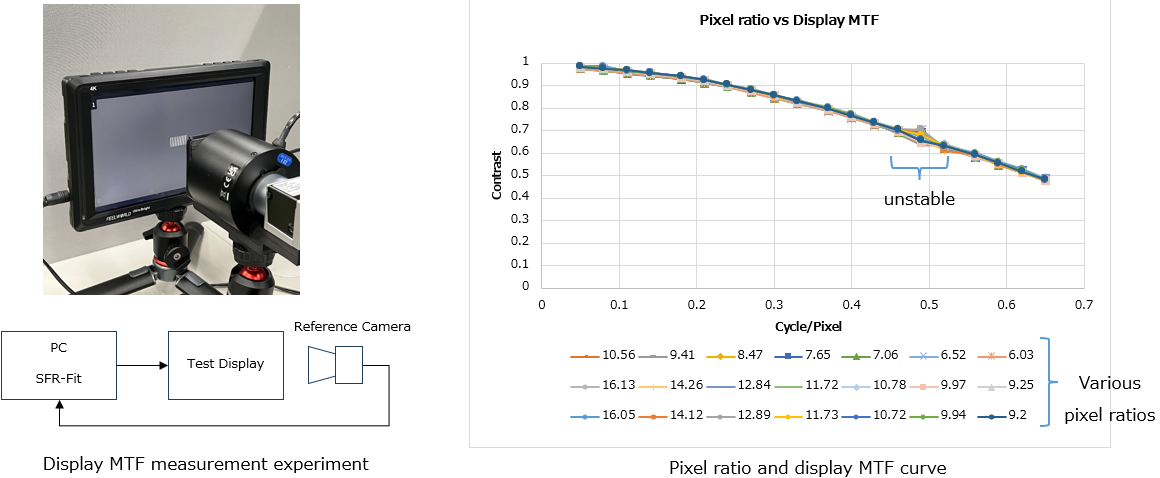
Measurements near Nyquist frequency
SFR-Fit CMS uses a sine wave bar chart to measure the MTF of a display, but when the pixel ratio is about 5 times, the contrast measurement error is up to 2%. Furthermore, due to the measurement principle, the measurement value is unstable near the Nyquist frequency. For this reason, the software skips the measurement points between 0.475 and 0.525C/P.
Measurement Repeatability
Because SFR-Fit uses a sine wave bar chart and MTF measurement using the least squares method, it can perform measurements that are less affected by the pixel structure of the display or image processing. As shown below, the repeatability of the measurement values is good, which is why we allow for measurement error.
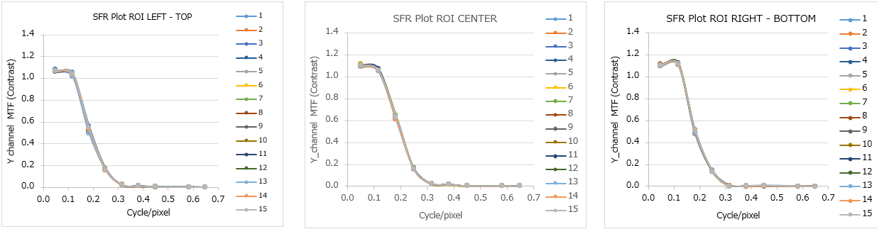
MTF repeatability of rear view monitor (measured 15 times). The graphs are almost identical.