Deprecated in Current Release
Requirements
Software operation
Defining Calibration Tasks
Definitions and Theory
In the Geometric Calibrator, a Calibration Task is a structure which contains all of the necessary information about the camera system and the test setup and images to produce calibration measurements.
An illustration of the components and structure of the Calibration Task is shown in Figure 1. A Task may be defined for a system with multiple cameras (Devices) and on multiple Test Capture setups.
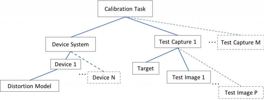
Figure 1, Calibration Task components diagram. At least one Device and Test Capture must be supplied, and at least one test Image per Test Capture. More may be defined as inputs to the Calibrator, as indicated here by the dashed lines.
All elements of this tree must be defined before calibration. Conversely, it may be said that a calibration will be done on the devices in this tree, using the evidence defined in it.
Define the system
In Geometric Calibrator module terminology, a Device is a camera model. A Device definition contains the parameters relevant for calibration of a projective camera: the sensor size and pixel pitch, the type of lens distortion function to fit, etc.
A Device System is made up of one or many Devices, and also contains information about their positioning. For multi-camera systems, one is chosen as a reference and the others’ positioning are defined relative to it.
Both the Device and Device System definitions fundamentally represent models or classes of real camera systems- e.g., you might make one Device definition for the class of “iPhone 5s cameras”. During a run of the calibration module, the Device and Device System definitions may be tagged with serial numbers or unique IDs to identify the calibration as pertaining to a particular camera, e.g., “my iPhone 5s”.
Define the evidence
The evidence used to calibrate the Devices comes from a defined set of Test Captures. These declare the Calibration Target used and the positions the camera system was in when capturing the associated Test Images.
Nominal input parameters vs estimated outputs
A number of the values provided as inputs to Imatest defined in the Calibration Task components are also subsequently returned as the calibration output values as well. These include:
- EFL
- distortion function
- inter-device extrinsics
- test capture position
The values supplied as input are typically the nominal values (e.g., from a lens spec sheet), and those produced as output of the module are refined estimates of the true parameters, based on the data. Providing the nominal values beforehand helps direct the calibration optimization, and is required for the high-accuracy calibrations that Imatest can produce.
Creating a Calibration Task
A Calibration Task to supply to the module can be created (or obtained) a number of ways:
- In Imatest Master, a Task can be created interactively by filling out the appropriate fields in the GUI.
- A Task may be loaded from a JSON-encoded *.calibration-task file (which may be saved out from Imatest Master).
- In Imatest IT, the Task can be assembled using provided helper classes and functions in the language of choice.
Each of the components which comprise the Task may also be saved independently, e.g. as *.device-system, *.calibration-target, etc., files. These may then be re-combined into a new Calibration Task as appropriate.
Example:
This is especially useful in a common use case: production-line calibration of many instances of the same type of device.
In this case, you already have a Device System definition which describes your camera system and Test Capture and Target definitions which describe your test setup.
As each Device Under Test (DUT) passes through the calibration station, it will produce a new set of image files, in a new location on disk. Combining these new file paths with associations to the Device which took each produces a new Test Image definition.
The new Test Images can be combined with the other, reused components to create a Calibration Task specific for this DUT.