About
Different software/programming languages may use different image coordinate systems [1, 2]. Although there are many possible image coordinate systems, four common ones have been defined within IEEE Std 2020-2024 [2]. The labeling of the image coordinate system facilitates interfacing between software/programming languages that use different image coordinate systems.
Factors
The following are factors of an image coordinate system.
| Factor | Description | Example(s) |
| Axis Ordering | The ordering of the pair of coordinates |
x, y (row, column); y, x (column, row) |
| Reference Pixel Index | The index of the reference pixel |
0; 1 |
| Reference Pixel Location | The location of the reference pixel |
Lower Left; Upper Left; Other |
| Positive x-axis Direction | The direction within the image that the x-coordinate increases |
Left; Right |
| Positive y-axis Direction | The direction within the image that the y-coordinate increases |
Up; Down |
| Integer Pixel Location | The within-pixel location of the integer index |
Pixel center; Other |
| Downsampling | The amount of downsampling performed |
None; 2×2; Other |
| Cropping | The amount of cropping performed |
No Cropping; Cropping |
Use within Imatest
Unless otherwise specified, Imatest uses an IEEE Std 2020 [2] Type IV image coordinate system.
Image Coordinate Systems
| IEEE Std 2020 [2] Type I | IEEE Std 2020 [2] Type II | IEEE Std 2020 [2] Type III | IEEE Std 2020 [2] Type IV | |
| Axis Ordering | x, y (row, column) | x, y (row, column) | x, y (row, column) | x, y (row, column) |
| Reference Pixel Index | 0 | 0 | 1 | 1 |
| Reference Pixel Location | Lower Left | Upper Left | Lower Left | Upper Left |
| Positive x-axis Direction | Right | Right | Right | Right |
| Positive y-axis Direction | Up | Down | Up | Down |
| Integer Pixel Location | Pixel Center | Pixel Center | Pixel Center | Pixel Center |
| Downsampling | None | None | None | None |
| Cropping | None | None | None | None |
| Example Usage | OpenCV |
MATLAB* Imatest |
* The MATLAB axis ordering is column, row.
Examples
The following examples illustrate various image coordinate systems for a 6-column by 4-row image. The reference pixel is marked in gray.
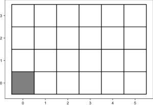 |
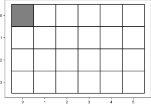 |
| IEEE Std 2020 [2] Type I | IEEE Std 2020 [2] Type II |
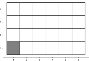 |
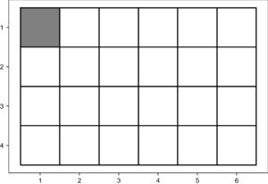 |
| IEEE Std 2020 [2] Type III | IEEE Std 2020 [2] Type IV |
References
[1] P. Romanczyk, “Validation methods for geometric camera calibration” in Proc. IS&T Int’l. Symp. on Electronic Imaging: Autonomous Vehicles and Machines, 2020, pp 150-1 – 150-6, https://doi.org/10.2352/ISSN.2470-1173.2020.16.AVM-150
[2] IEEE Std 2020-2024. “IEEE Standard for Automotive System Image Quality”. DOI: 10.1109/IEEESTD.2024.10935839


