Monitor patterns for Light Falloff, SFR, Distortion, and monitor calibration
|
There have been some significant enhancements to Screen Patterns in Imatest 24.1: SFRreg patterns, Checkerboard patterns with adjustable contrast, and a simplified 5-row SFRplus pattern with five rows have been added. A much larger selection of patterns is now available on Test Charts, which can create |
Introduction
Screen Patterns displays a variety of test patterns on monitors, preferably on LCD flat screen monitors. It may become more useful as cost-effective ultra-high resolution (4k+) monitors become available. It is opened by clicking on on the right of the Imatest main window. Most patterns (except perhaps Monitor calibration) perform best with the window maximized. You may need to redraw the pattern after maximizing (or resizing) it by selecting the pattern or changing one of the settings. These patterns are offered as a convenient alternative to the printed patterns created by Test Charts.
|
Before using a monitor, make sure it doesn’t flicker. Some monitors— especially in laptops— use time domain multiplexing to achieve a good color gamut, and they may not be suitable. A quick way to find this out is to look at the preview image in a camera phone. If it contains banding, the monitor is probably not a good choice. Here is link for a flicker test from a Wirecutter 4k monitor review. How to test my Monitor for PWM flicker? |
The test patterns fall into two categories:
- patterns that can be photographed for analysis by Imatest modules, including Light Falloff, Distortion, and SFR, and
- patterns for checking monitor calibration, estimating monitor performance (and a few other uses).
The pattern is selected with a dropdown menu in the bottom-middle of the Screen Patterns window. The patterns intended for photographing tend to work poorly with CRTs because of the raster scan, which can cause nonuniform illumination and may cause inconsistent readings with some DSLR metering systems (like my Canon EOS-40D). The patterns are summarized in the table below.
| Patterns to be photographed for Imatest analysis | |
| Light Falloff (blank) | Blank screen for obtaining even illumination. Superior to other low-cost techniques. |
| SFR Quadrants | SFR quadrant pattern: you must tilt the screen relative to the camera to photograph it. |
| SFR Quads: Global H,S | SFR quadrant pattern where darker (quadrant) areas have the same H and S as the highlight area (normally the darker area is neutral). |
| Distortion grid Distortion grid inverted |
A large flat screen monitor is a definite asset with this module. No longer recommended: Checkerboard is better. |
| Zone plate (sine) Zone plate (bar) |
For finding optimum camera focus using strongly visible moiré patterns. Sine and Bar options are available. |
| SMPTE color bars |
Widely used for video adjustments. May be used for a simple visual analysis of color quality. |
| Slanted edges |
Similar to the patterns in SFR SVG Test charts. 1, 2, and 3 row patterns are available and also simplified SFRplus charts with 3 or 5 rows of slanted squares. Not as sharp as the SFR quadrant patterns (with vertical, horizontal edges). Use with care; not for testing high resolution cameras. |
| Colorchecker and Grayscale charts |
Simulated Colorchecker and grayscale step charts: 20 steps with 0.10 and 0.15 density steps (1.95 and 3.85 maximum densities). Not recommended for camera testing unless the screen is very well-calibrated. |
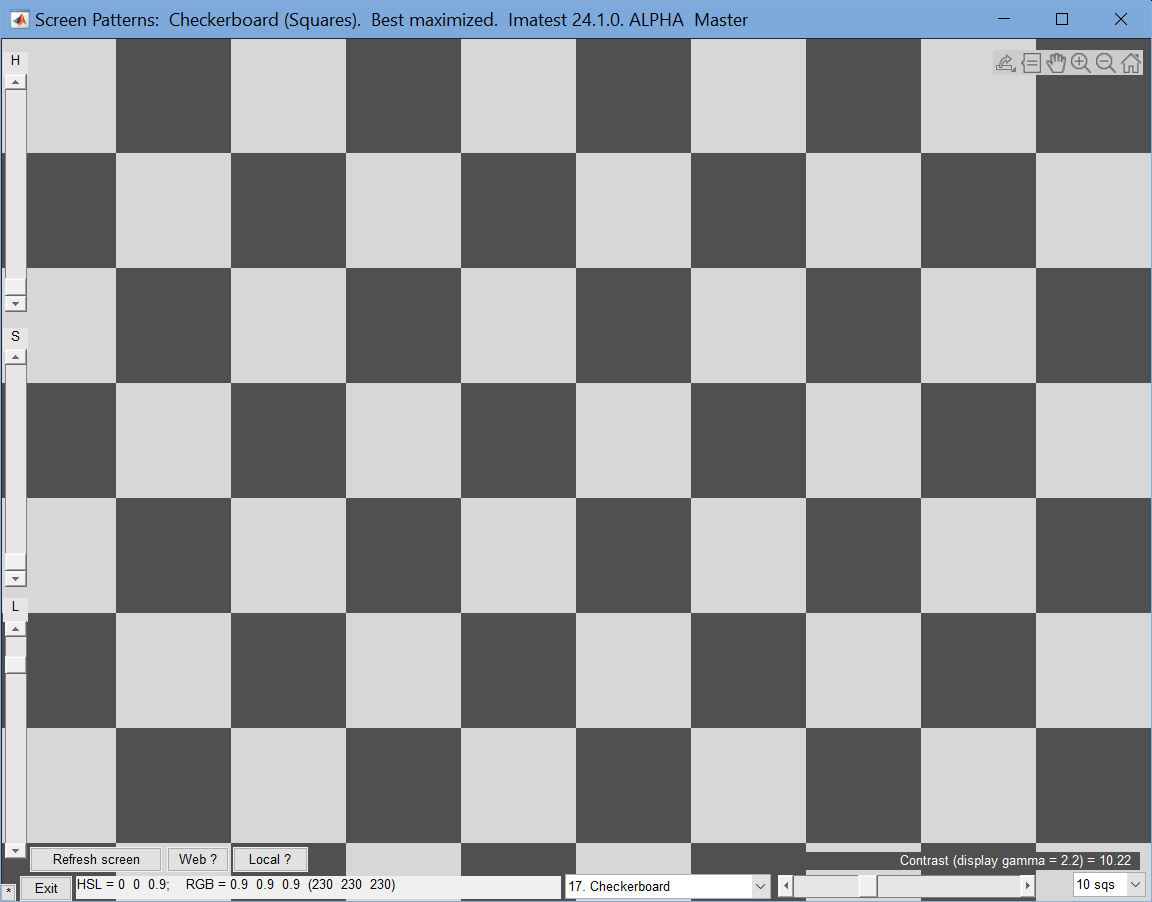
| Checkerboard (squares) | Checkerboard pattern for measuring MTF (if tilted) and distortion with the Checkerboard module |
| Miscellaneous: for monitor calibration or camera adjustment | |
| Monitor calibration | This selection contains several patterns:A gamma/black level test pattern that allows you to estimate gamma,A monitor gamma pattern that looks uniform when the adjacent slider is set to the correct gamma, andTwo HSL rainbow patterns that can be used for a rough visual estimate of color quality. |
| Monitor gamma only | The monitor gamma pattern fills the entire screen. It is adjusted with a slider at the bottom-center. It allows you to determine gamma with high accuracy and see variations across the screen. |
Adding charts to Screen Patterns is relatively straightforward. Please contact us if you’d like to have one added.
Several patterns display the W x H screen size in the lower right corner. H is smaller than the total screen size by about 21 pixels: about the height of the upper toolbar.
Workflow
- Open the Screen Patterns module. From the legacy Imatest window, use the Utility dropdown menu or the Misc. tab in the box on the right.
- Select the pattern to be displayed on the screen and make the desired settings.
- For most patterns, resize (generally Maximize) the Screen Patterns window.
- Press Refresh screen (button on the lower-left) to fill the resized window with the desired.
- Press the tiny * button on the extreme lower-left. It’s very inconspicuous. This makes the settings disappear, but the inconspicuous * button remains. Press it to bring back the settings.
Light Falloff pattern
If you have a flat screen LCD monitor, the Screen Patterns Light Falloff pattern is a good way of obtaining an even, uniform image. This is the first pattern that appears when you open Screen Patterns.
Light Falloff image (initial screen at startup)
Hue, Saturation, and Lightness (H, S, and L, which default to 0,0,1) can be adjusted using the sliders on the far left. HSL and RGB values are displayed at the bottom. For Flatfield photograph it at a distance of 1-3 inches (2-8 cm). It may be best for the camera to be unfocused. (Thanks to Jonathan Sachs for this suggestion.)
For extreme wide angle lenses or laptop screens with a limited viewing angle, an additional diffuser may be needed. Opal diffusing glass mounted close to the lens, available in the US from Edmund Optics, is a good choice.
SFR quadrants and SFRreg
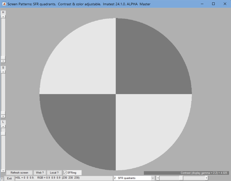
SFR quadrant pattern, set for SFRreg. Contrast ≅ 4:1
There are two quadrant patterns for SFR measurements:
- SFR Quadrants, where the darker area is neutral, and
- SFR Quads: Global H,S, where the darker area has the same Hue (H) and Saturation (S) as the highlight area. If S is 0, it doesn’t matter which one is chosen.
Vertical and horizontal bar patterns are also available. They’re near the bottom of the selection list.
Checking the SFRreg checkbox (bottom, left of center) creates a middle-tone circular mask, turning the quadrants into an SFRreg pattern, shown on the right.
The monitor should be tilted (typically around 5 degrees) with respect to the camera when this pattern is used for SFR measurements to minimize pixilation. This use of this pattern is discussed in Imatest SFR LCD target.
Hue (H), Saturation (S), and Lightness (L) can be controlled with the sliders on the far left. Contrast (Quadrant Lightness) can be controlled with the slider on the bottom-right. The contrast for display gamma = 2.2 is shown on the lower right. In this case, the lower right slider has been adjusted for a 4:1 image contrast. The L slider on the left can be set to 0.5 for maximum color saturation (it’s usually kept at 0).
Distortion grid for the legacy Distortion program: \
Checkerboard is now recommended.
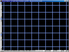
 Distortion grid
The distortion grid creates images for the legacy Imatest Distortion module consists of black lines on a white or colored background. (Checkerboard patterns with the Checkerboard module is strongly preferred.)
Three key settings are located on the lower-right: the number horizontal lines (H-L), the number of vertical lines (V-L), and the line width in pixels (W). The choice depends on the amount of distortion and the aspect ratio of the screen. The first (default) vertical setting is Square: vertical and horizontal lines have identical spacing. 7-9 horizontal lines and 10-15 vertical lines are typical. The Checkerboard (Squares) pattern (below) with the Checkerboard program is more robust
Distortion grid inverted
Normally the lines are black and highlight (background) H, S, and L can be controlled with the sliders on the far left. If Distortion grid inverted is selected, the background will be black and the H, S, and L sliders will adjust the line color.
Monitor calibration
This selection contains several patterns that enable you to check your monitor’s calibration. The gamma patterns (left and middle) must be viewed on a monitor; they do not work in printed media. restores the default values, H = 0, S = 0, L = 1, and Gamma = 2.2.
Note that laptop LCD screens cannot be accurately calibrated because gamma is a strong function of vertical viewing angle.
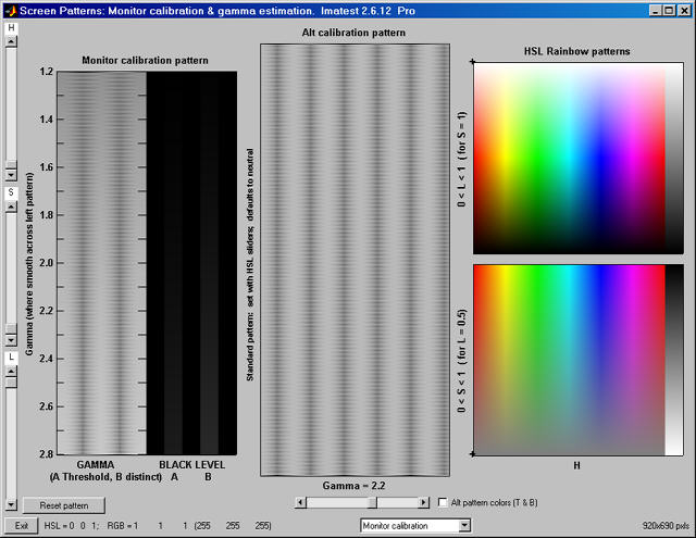
Monitor Calibration patterns (the serrated vertical bands
in the left and middle patterns are not what you see.)
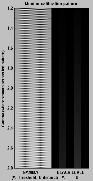
Left: Gamma and black level chart adapted from normankoren.com.
This chart enables (shown below) you to set the black level (brightness) and estimate display gamma over a range of 1.2 to 2.8 with accuracy close to ±0.05. The gamma pattern is on the left; the black level pattern is on the right. Before using the chart, CRT monitors should be turned for on for at least 15 minutes. For flat screen (LCD) monitors, Screen resolution should be set to the monitor’s native resolution (right-click on the wallpaper, Properties, Settings).
| Display gamma is the relation between pixel level and screen luminance. It comes from the equation, Luminance = (pixel level)gamma |
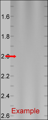
Gamma is estimated by locating the position where the average luminance across the gamma pattern is constant. The corresponding gamma is shown on the left. You should be far enough from your monitor so the line pattern is not clearly visible. The example below shows what to look for.
|
This chart features gradual density changes along horizontal scan lines (thus eliminating CRT risetime problems).
We’ll be happy to grant permission to reproduce this pattern on your website if you e-mail us, give credit and a link to this page. |
 |
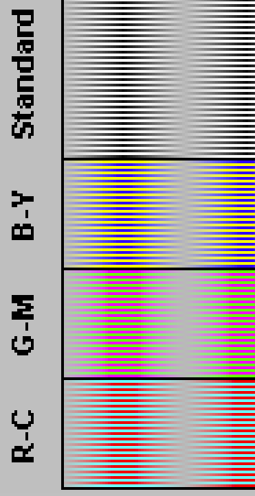
Alt calibration pattern (middle) enlarged 4x;Alt pattern colors (T & B) checked
Black level (brightness) Your monitor’s brightness control (which should actually be called black level) can be adjusted using the mostly black pattern on the right side of the chart. This pattern contains two dark gray vertical bars, A and B, which increase in luminance with increasing gamma. (If you can’t see them, your black level is way low.) The left bar (A) should be just above the threshold of visibility opposite your chosen gamma (2.2 or 1.8)– it should be invisible where gamma is lower by about 0.3. The right bar (B) should be distinctly visible: brighter than (A), but still very dark.
There is considerable interaction between the brightness and gamma settings in CRTs— increasing brightness decreases gamma– so you may have to go back and forth two or three times. There is less interaction between Contrast and gamma. The vertical bars correspond to normalized luminances of 0.002 and 0.006 at the specified gamma.
The image on the right shows the middle gamma pattern enlarged 4x. The upper part of this image, to the right of Standard, uses the same black-to-white sinusoidal variation as the Gamma and black level chart. The color patterns appear when the Alt pattern colors (T & B) box, located just to the right of the Gamma slider, is checked
When this image is displayed normal size (not enlarged; below) on a good quality monitor, the R-C, G-M, B-Y, and Standard patterns appear nearly identical.
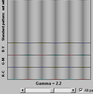
Middle (gamma) pattern,
showing R-C, G-M, B-Y color bands
Middle: Gamma pattern. This pattern will look uniform when the gamma slider (just below it) is set to the correct monitor gamma. It is very sensitive: it can measure gamma to better than ±0.05 accuracy: The spatial frequency of vertical bands is set close to the the frequency where the human eye’s Contrast Sensitivity Function is maximum for typical viewing situations.
The patterns on the right will appear uniform
if monitor gamma is 2.2.
A checkbox labeled Alt pattern colors (T & B) is located just to the right of the Gamma slider. When this box is checked, three bands (six total) appear near the top and bottom of the gamma pattern. Instead of the standard gamma pattern’s normal black-to-white sinusoidal variation, individual lines vary from Blue-to-Yellow, Green-to-Magenta, and Red-to-Cyan. In a normally functioning monitor these bands appear the same neutral gray as the standard pattern, but they could look strange in a defective or poorly calibrated monitor. Unchecking this box speeds image refresh.
Right: HSL rainbow patterns. These patterns are used for a rough visual estimate of the monitor’s color performance. They should appear well-saturated and have smooth color and tonal gradations (no abrupt changes). Laptops typically look very different from well-calibrated LCD or CRT monitors.
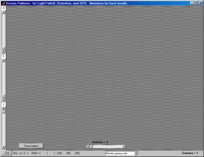
Full screen gamma pattern for viewing screen
nonuniformities. (Actual image looks very different)
Gamma pattern (full screen)
The full screen gamma pattern allows you to examine screen uniformity in fine detail. It is identical to the gamma pattern in the middle of the Monitor calibration display, described above. Gamma can be estimated with excellent accuracy: to better than ±0.5.Hightlight H, S, and L can be controlled with the sliders on the far left. restores default values: H = 0, S = 0, L = 1, and Gamma = 2.2.
Zone plate
The zone plate (not analyzed by Imatest) is useful for testing camera focus in cameras with live view because it produces highly visible moiré patterns when it is photographed or resized; the stronger the moiré the better the focus. Northlight Images describes a way of using the zone plate to tune the focus of the Canon 1Ds Mark III. The Squares patterns below are also designed to generate moiré.
Screen Patterns has two versions of the zone plate: sine (shown below) and bar (with stronger edges: possibly better for focusing).
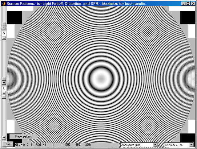
Zone plate pattern
The maximum spatial frequency can be adjusted with the menu on the bottom right. 1/4 cycles/pixel (half-Nyquist) is the default. Highlight H, S, and L can be controlled with the sliders on the far left. (The H slider was obscured when the image was resized.) restores default values: H = 0, S = 0, L = 1 and also redraws the image. Learn more about zone plates from Bart van der Wolf.
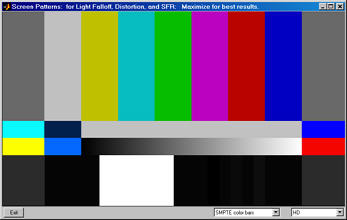
SMPTE color bars
SMPTE color bars are widely used in the video industry for calibrating TVs and monitors. They’re included in Screen Patterns as an experiment— to see if customers find them useful. It’s straightforward to add charts to Screen Patterns: please contact us if you have a chart you’d like added.
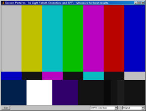 SMPTE color bar (original) |
 SMPTE color bar (HD) |
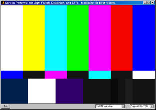 SMPTE color bar (original LIGHTENED): upper section lightened |
|
The pixel values for the charts are from the Wikipedia page, SMPTE color bars. We are not certain of their correctness. Many pages interpret these bars differently (the colors in the top row are often brighter). Both the original and HD charts can be displayed with the top row of colors lightened.
Slanted edges (1, 2, 3 rows), and 3, 5 rows: (simplified SFRplus)
These slanted edge patterns are similar to the patterns in SFR SVG Test charts. 1, 2, and 3 row patterns without bars and 3 or 5 row patterns (with SFRplus distortion bars) are available. H, S, and L (Hue Saturation, and Lightness) can be adjusted for the highlights (i.e., the background), and L can be adjusted for the patches, which retain the same H and S values as the background, similar to SFR Quads: Global H,S , described in SFR quadrant patterns, above. Contrast is displayed on the lower right.
It is important to note that these edges are not as sharp as the vertical and horizontal edges in SFR quadrant patterns because a small amount of anti-aliasing must be applied to avoid jagged edges. These patterns should not fill the frame when testing high resolution cameras, where large printed charts work far better, but they may be useful in testing monitors, projectors, and low resolution cameras. If all cases, you should carefully analyze the relative contributions of the display, camera, and lens to the final MTF measurement, i.e., you should know precisely what you are measuring.
 2-row slanted-edge pattern, 20:1 contrast |
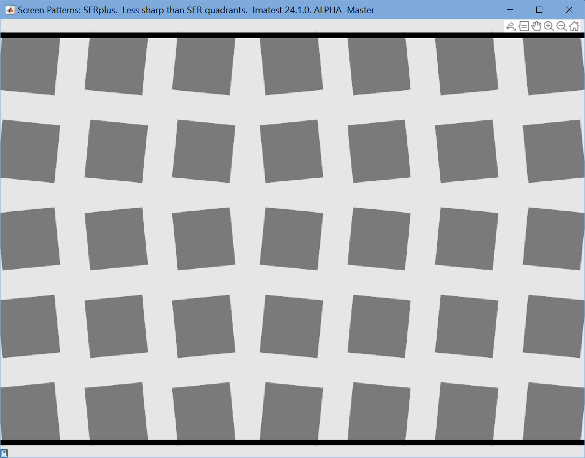 5-row SFRplus slanted-edge pattern, 4:1 contrast 5-row SFRplus slanted-edge pattern, 4:1 contrastThe tiny * button, extreme lower-left, has been pressed to turn off settings. |
 Colorchecker and grayscale charts
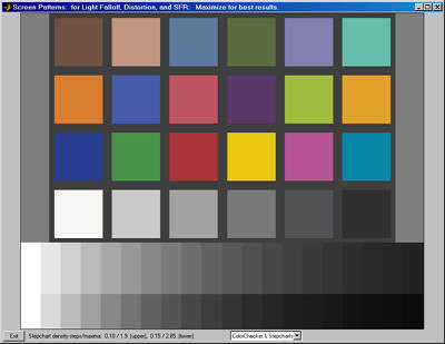
A simulated ColorChecker and two step charts are displayed. sRGB color space (gamma = 2.2) is assumed. The upper stepchart has a density increment of 0.10 and range of 1.9 (79:1 contrast ratio); the lower stepchart has a density increment of 0.15 and range of 2.85 (708:1 contrast ratio).
Unless your monitor is exceptionally well-calibrated, this pattern should not be used for testing cameras: a real reflective Colorchecker gives superior results. It can be used to make a simple visual estimate of display quality, and it may also be useful for analyzing the response of displays or projected images when photographed with a well-profiled camera.
Colorchecker & grayscale charts (ΔD = 0.10 (upper), 0.15 (lower))
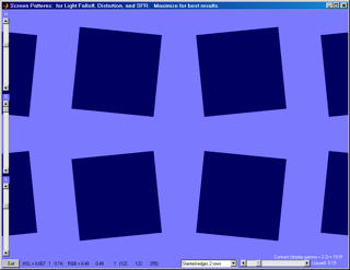
Checkerboard (squares)Can be used to measure distortion or MTF (with the screen tilted ~5º) with the Checkerboard module. Contrast can be adjusted on the lower-right. The spacing between squares (1-30) or the number of squares (for Squares (checkerboard) only) can be selected in the dropdown menu in the lower right. |
 |
Squares with focus patternWe don’t remember designing this pattern. (It was a long time ago.) But we found this description. These patterns are specifically designed for creating moiré fringing for measuring camera focus with a camera’s Live View feature. See Bart van der Wolf’s post on Open Photography Forums and related material on Northlight Images. The Squares (checkerboard) pattern (left, below) is an alternative to the grid chart in Distortion. |
 |
