Imatest Pass/Fail Operation and Reference
Introduction
Imatest can return pass/fail (P/F) results for applications (such as industrial camera testing) where they are required. Although pass/fail is primarily intended for Imatest IT (Industrial Testing; DLL and EXE), it works with GUI-based versions of Imatest (except for Studio), where the Pass/Fail monitor can be particularly useful for previewing the results of P/F threshold settings for Imatest IT.
Getting started – Summary – Pass/fail settings file – Pass/Fail Reference
Slanted-edge (SFRplus, etc.) settings – Sharpness (Random and Star) – Blemish and Uniformity
Colorcheck – Distortion – Color/Tone – Stepchart
Getting started with Pass/Fail
|
Summary
- Pass/fail settings— minima, maxima, or limits— are stored in their own ini file (separate from the standard ini file: imatest-v2.ini or other) in the usual ini file format;
[section]
parameter = value
; Comments start with a semicolon.
[section] corresponds to the module, where supported modules are listed below. Because this file contains values for the camera specification, it is often called a “spec.ini” file. Please contact us if a setting you need is not listed: it is relatively straightforward to add it.
- The pass/fail ini file is maintained and updated by the customer using a text editor or the Imatest INI File Editor.
- The full path name to the pass/fail ini file is entered in the [api] section of the main ini file with a statement of the form,
Pass/Fail Monitor
[api]
passFail = fullPathName.
This can be done by clicking Settings, IT & Pass/Fail settings in the Imatest main window, then entering the full path name in the appropriate box.
- Information about the Unit Under Test (UUT) must be passed to Imatest in the same JSON object (string) used to pass image array properties to Imatest DLL modules.
- The UUT part number, serial number, pass/fail settings, results value, and pass/fail results (1 or 0) are returned to the calling program in a JSON object.
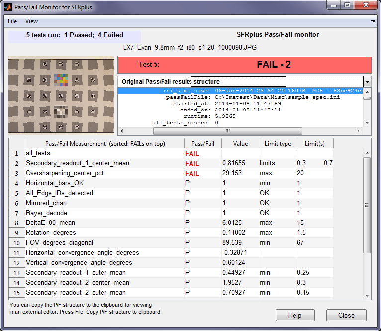
- A Pass/Fail Monitor (shown on the right) can display Pass/Fail results and (if selected) history in realtime in GUI versions of Imatest, immediately after the results are calculated.
| Section | Description |
| [colorcheck] | for Colorcheck |
| [distortion] | for Distortion |
| [multi] | Color/Tone Interactive and Color/Tone Auto color/grayscale modules. There are similar entries in [colorcheck] and [stepchart]. |
| [sfr] | [sfr] measurements are a subset of SFRplus |
| [sfrplus] | includes [sfr] measurements. |
| [sharpness] | for Random/Dead Leaves (Spilled Coins) and Star; either fixed or Rescharts modules |
| [stepchart] | for Stepchart |
| [flatfield] | Measurements of a uniform flat field for blemishes and nonuniformities. |
Pass/Fail settings file
Pass/Fail settings— minimum, maximum, or limit (min, max, or limits) values for individual measurements— are stored in an ini file that is separate from the main ini settings file so it can be protected from tampering, if needed. It can be in a protected folder that requires administrator access to write.
We strongly recommend that the Pass/Fail settings file contains comment lines (starting with ;) that contain the secondary readout settings and frequency units (if applicable). It can be useful if they contain a description of the device to be tested.
It has standard ini file format with sections corresponding to Imatest modules, listed in the Pass/Fail file summary. Most entries have one of three suffixes:
| _min | (for minimum value) |
| _max | (for maximum value) |
| _limits | (for two values: minimum and maximum) |
There are a few settings with different formats— kept for backwards compatibility.
Here is an example. Parameters are listed in the Pass/Fail Reference, below.
[sfrplus]
MTF50P_ratio_min = .5
MTF50P_CP_weighted_mean_min = .13
Rotation_degrees_max = 1
FOV_degrees_diagonal_min = 62
Convergence_angle_max = 5
Secondary_readout_1_center_mean_min = .2
Secondary_readout_1_outer_mean_min = .2
Secondary_readout_2_center_mean_min = .2
Secondary_readout_2_outer_mean_min = .2
[flatfield]
Dead_pixels_max = 10
Hot_pixels_max = 10
Optical_center_offset_max = 50
Relative_illumination_worst_corner_pct_min = 40
Uniformity_RoverG_corners_pct_max = 10
Uniformity_BoverG_corners_pct_max = 10
Blemish_size_pixels = 20 50
Blemish_maximum_count = 2 1
For example, MTF50P_ratio_min = .5 sets the minimum acceptable value for (minimum MTF50P)/(maximum MTF50P) (taken over all the selected regions) to 0.5.
The customer must update this file to meet his needs. Additional measurements will be added on request.
Pass/Fail Reference
| Slanted-edge modules [sfrplus], [esfriso], [sfrreg], [checkerboard], and [sfr] |
||
|
[sfrreg], [checkerboard], and [sfr] are subsets of SFRplus. |
||
| Variable with typical parameter | Description | |
| Chart_mean_pixel_level_bounds = 100 200 |
Minimum and maximum mean pixel levels for the chart, measured in the middle third (ninth by area) of the chart. Set to avoid cheating by over (or under) exposing so edges saturate (sharp corners), resulting in improved MTF. | |
| Chart_radial_pixel_shift_max = 0 |
(+eC) |
Offset of chart center (from image center) in pixels. |
| Dynamic_Range_ISO_15739_at_density_2_min | (e) | ISO 15739 Dynamic Range derived from the grayscale patch with density closest to 2.0 (eSFR ISO-only) |
| Low_pixel_saturation_fraction_max |
Maximum fraction (of pixels) within 2% of zero level | |
| Gamma_from_slanted_edges_mean_min | Minimum value of the mean gamma (contrast), measured from all slanted-edges where gamma can be measured (chart contrast ratio must be entered). A low value indicates fogging. Not calculated if the light and dark regions are too small. This can be an issue with SFRreg with large edge angles. We recommend Wider or Widest ROI width (instead of Normal). | |
| Gamma_from_slanted_edges_min_min | Minimum value of the minimum gamma (contrast), measured from all slanted-edges (chart contrast ratio must be entered). A low value indicates fogging. | |
| Gamma_from_stepchart_limits |
(e) | Gamma (minimum and maximum limits) from the eSFR ISO grayscale pattern |
| High_pixel_saturation_fraction_max | Maximum fraction (of pixels) within 1% of maximum level (typically 255) | |
| MTF50_max_max | Maximum value of MTF50 (in selected units) for all selected edges | |
| MTF50_mean_min | Minimum value of the mean of MTF50 (in selected units), from all selected edges. | |
| MTF50_min_min | Minimum value of MTF50 (in selected units) for all selected edges. | |
| MTF50P_max_max | Maximum value of MTF50P (in selected units) for all selected edges. | |
| MTF50P_mean_min | Minimum value of the mean of MTF50P (in selected units), from all selected edges. | |
| MTF50P_min_min | Minimum value of MTF50P (in selected units) for all selected edges. | |
| MTF50P_ratio_min = .5 |
Minimum ratio of the minimum to maximum MTF50P (spatial frequency where contrast falls to half its peak value). A low value indicates poor lens quality or possibly significant lens tilt. | |
| MTF50P_CP_weighted_mean_min = .13 | Weighted mean MTF50P in Cycles/Pixel. | |
| Relative_illumination_from_ROIs_min | Minimum Relative illumination (min/max) from mean pixel levels of slanted-edge ROIs. | |
| Rotation_degrees_max = 1 |
(+eC) |
Image rotation in degrees, measured from the top and bottom distortion bars. The absolute value is used for Pass/Fail. Note that if the chart is upside-down (vertically mirrored or rotated 180 degrees) 180 will be added to the rotation, which will generally result in a failure for this measurement. |
| FOV_degrees_diagonal_min = 62 |
(+eC) |
The diagonal Field of View in degrees |
| Convergence_angle_max = 5 | (+eC) |
Maximum allowed convergence angle (both Horizontal and Vertical are measured). A measure of keystone distortion. |
| Secondary_readout_1_all_min_min |
Minimum allowed value of the mean of Secondary readout 1 anywhere in the image. Secondary readouts are described Here. Secondary readout ini file settings are listed in the Imatest INI file reference. | |
| Secondary_readout_1_center_mean_min = .2 | The minimum allowed value of the mean of Secondary readout 1 in the center region (<30% of the center-to-corner distance). | |
| Secondary_readout_1_outer_mean_min = .2 | Minimum allowed value of the mean of Secondary readout 1 in the outer region (≥30% of the center-to-corner distance; includes partway (30-75% ) and corner (>75%) regions). (For eSFR ISO, part-way is 30-68% and corner is >68%.) |
|
| Secondary_readout_2_all_min_min |
Minimum allowed value of the mean of Secondary readout 2 anywhere in the image. | |
| Secondary_readout_2_center_mean_min = .2 | Minimum allowed value of the mean of Secondary readout 2 in the center region (up to 30% of the center-to-corner distance). | |
| Secondary_readout_2_outer_mean_min = .2 | Minimum allowed value of the mean of Secondary readout 2 in the outer region (≥30% of the center-to-corner distance; includes the partway and corner regions) | |
| Secondary_readout_1_outer_min_min = .2 | Minimum allowed value of the minimum value of Secondary readout 1 in the outer region (≥30% of the center-to-corner distance) | |
| Secondary_readout_2_outer_min_min = .2 | Minimum allowed value of the minimum value of Secondary readout 2 in the outer region | |
| Secondary_readout_1_partway_mean_min = .2 | Minimum allowed value of the mean value of Secondary readout 1 in the partway region (30-75% of the center-to-corner distance) | |
| Secondary_readout_2_partway_mean_min = .2 | Minimum allowed value of the mean value of Secondary readout 2 in the partway region | |
| SMIA_TV_distortion_limits | (+eC) | Minimum and maximum allowed value of SMIA TV distortion. |
| snr_bw_min | (e) | Minimum value of SNR BW: \( SNR_{BW} = 20 \log_{10}\bigl( \frac{S_{WHITE} – S_{BLACK}}{N_{MID}} \bigr) \) See www.imatest.com/docs/noise/#snr_bw This measurement is scene-referenced, i.e., it changes little when image contrast changes. |
| Y_SNR_dB_mean_except_ends_min |
(e) | Minimum value of SNR (dB) from the grayscale step chart, excluding the two lightest and darkest patches. Y (luminance) channel for color images. Proportional to image contrast. |
| Horizontal_bars_OK_min = 1 (+) | (+) | Test for properly detected top and bottom bars (present with no significant gaps). |
| All_Edge_IDs_detected = 1 (+) | Verify that all Edge_ID’s that are specified in the edge ID file are detected | |
| Mirrored_chart = 1 | (+e) |
Test for mirrored (Left-Right or Top-Bottom) image (fails mirrored images) if entered and the chart contains a grayscale step chart below the center square and stepchart = 1 in the [sfrplus] section of the main ini file. |
| Bayer_decode = 1 | (+e) |
Test for correct Bayer pattern decoding (fails if incorrect) if entered and the chart contains color patches above the center square and colorchart = 1 in the [sfrplus] section of the main ini file. |
| Color_expected_detected = 1 | (+e) |
A color pattern is expected above the chart center when colorchart = 1 in the [sfrplus] section of the main ini file. If the color pattern is not present, this test will fail. This could indicate bad chart positioning or simply that the color pattern is not present in the test chart. |
| DeltaE_00_mean_max = 10 | (+e) |
ΔE 2000 Color accuracy. For best results use a color reference file generated from multicharts. |
| Stepchart_expected_detected = 1 | (+e) |
A grayscale stepchart is expected below the chart center when stepchart = 1 in the [sfrplus] section of the main ini file. If the stepchart is not present, this test will fail. This could indicate bad chart positioning or simply that the grayscale stepchart is not present in the test chart (a rare occurrence because it’s in most standard charts, except for the chrome-on-glass chart). |
| upside_down = 1 |
(+e) |
If set, fail the image if an upside-down condition is detected. |
| passfail_ini_file_date = (manually entered date) | Optional indicator of pass/fail date. Another result appears in the output: passfail_ini_time_size, which contains the time the file was modified and the size in bytes. | |
| [sharpness] for Random and Star modules (fixed or Rescharts) Related documents: Random/Dead Leaves (Spilled Coins) | Star chart |
||
| MTF50_min = .25 |
||
| Oversharpening_pct_limits -20 25 |
||
| Secondary_readout_1_min | ||
| Secondary_readout_2_min | ||
| Secondary_readout_1_limits | ||
| Secondary_readout_2_limits | ||
| Oversharpening_pct_max = 25 |
Maximum oversharpening (Overshoot is not defined for the supported modules.) | |
| Acutance_min = 80 |
CPIQ Acutance minimum | |
| Related documents: Using Flatfield Blemish Detect | Flatfield INI file reference |
||
| Dead_pixels_max = 10 | Maximum number of dead pixels allowed. Thresholds for dead pixel detection (% or absolute) are set in the [flatfield] section of the ini file. | |
| Dead_pixel_clusters_max = 0 |
Maximum number of dead pixel clusters allowed, where a cluster is defined as two or more adjacent dead pixels. Overrides the calcluster setting in the standard ini file: calcluster(2) is set to 1 if entered. |
|
| Defective_pixels_max_count = 10 |
Maximum sum of hot + dead pixels | |
| Hot_pixels_max = 10 | Maximum number of hot pixels allows. Thresholds for hot pixel detection (% or absolute) are set in the [flatfield] section of the ini file. | |
| Hot_pixel_clusters_max = 0 |
Maximum number of hot pixel clusters allowed, where a cluster is defined as two or more adjacent hot pixels. Overrides the calcluster setting in the standard ini file: calcluster(1) is set to 1 if entered. | |
| Optical_center_offset_max = 50 Optical_center_offset_X_max = 50 Optical_center_offset_Y_max = 50 |
Maximum offset in pixels of the optical center (location of highest luminance) from the center of the image. To minimize the effects of noise, X and Y optical centers are defined using the centroid of the of the curve between the points where the smoothed values fall below 95% of the maximum. (The actual maximum is highly susceptible to noise since it’s very broad.) | |
| Relative_illumination_worst_corner_pct_min = 40 | Minimum corner region luminance divided by the maximum luminance of the smoothed image. | |
| Uniformity_RoverG_corners_pct_max = 10 | Maximum R/G corner nonuniformity = 100%(RGmax – RGmin)/RGmax, where RGmax = maximum R/G ratio in the four corners; RGmin = minimum R/G ratio in the four corners. | |
| Uniformity_BoverG_corners_pct_max = 10 | Maximum B/G corner nonuniformity = 100%(BGmax – BGmin)/BGmax, where BGmax = maximum B/G ratio in the four corners; BGmin = minimum B/G ratio in the four corners. | |
| R_div_G_ctr_corner_diff_pct_max | [v4.3+ Bayer RAW] Maximum R/G center & corner difference % = 100%(RGmax – RGmin)/RGmax, where RGmax = maximum R/G ratio in center & corners; RGmin = minimum R/G ratio in center & corners. | |
| R_div_G_ctr_corner_diff_pct_mean_max | [v4.3+ Bayer RAW] Maximum R/G center & corner difference % = 100%(RGmax – RGmean)/RGmax, where RGmax = maximum R/G ratio in center & corners; RGmean = average R/G ratio in corners. | |
| B_div_G_ctr_corner_diff_pct_max | [v4.3+ Bayer RAW] Maximum B/G center & corner difference % = 100%(BGmax – BGmin)/BRGmax, where BGmax = maximum B/G ratio in center & corners; BGmin = minimum B/G ratio in center & corners. | |
| B_div_G_ctr_corner_diff_pct_mean_max | [v4.3+ Bayer RAW] Maximum B/G center & corner difference % = 100%(BGmax – BGmean)/BGmax, where BGmax = maximum B/G ratio in center & corners; BGmean = average B/G ratio in corners. | |
| R_div_B_ctr_corner_diff_pct_max | [v4.3+ Bayer RAW] Maximum R/B center & corner difference % = 100%(RBmax – RBmin)/RBmax, where RBmax = maximum R/B ratio in center & corners; RBmin = minimum R/B ratio in center & corners. | |
| R_div_B_ctr_corner_diff_pct_mean_max | [v4.3+ Bayer RAW] Maximum R/B center & corner difference % = 100%(RBmax – RBmean)/RBmax, where RBmax = maximum R/B ratio in center & corners; RBmean = average R/B ratio in corners. | |
| Center_Gb_Gr_variation_pct_max | [v4.3+ Bayer RAW] Maximum Center patch Gb – Gr difference % = 100% Abs(Gbmean-Grmean)/Average(Gbmean, Grmean) | |
| Corner_Gb_Gr_variation_pct_max | [v4.3+ Bayer RAW] Maximum Corner patch Gb – Gr difference % = 100% Abs(Gbmean-Grmean)/Average(Gbmean, Grmean) | |
| Center_R_div_G_unnorml_limits | Range [min max] of allowable values for center R/G ratio. Values are unnormalized. | |
| Center_B_div_G_unnorml_limits | Range [min max] of allowable values for center B/G ratio. Values are unnormalized. | |
| Center_R_mean_max | [v4.3+ Bayer RAW] Center patch Red channel mean pixel level maximum | |
| Center_R_mean_min | [v4.3+ Bayer RAW] Center patch Red channel mean pixel level minimum | |
| Center_Gb_mean_max | [v4.3+ Bayer RAW] Center patch Green (blue) channel mean pixel level maximum | |
| Center_Gb_mean_min | [v4.3+ Bayer RAW] Center patch Green (blue) channel mean pixel level minimum | |
| Center_Gr_mean_max | [v4.3+ Bayer RAW] Center patch Green (red) channel mean pixel level maximum | |
| Center_Gr_mean_min | [v4.3+ Bayer RAW] Center patch Green (red) channel mean pixel level minimum | |
| Center_B_mean_max | [v4.3+ Bayer RAW] Center patch Blue channel mean pixel level maximum | |
| Center_B_mean_min | [v4.3+ Bayer RAW] Center patch Blue channel mean pixel level maximum | |
| Center_R_std_max | [v4.3+ Bayer RAW] Center patch Red channel standard deviation maximum | |
| Center_Gb_std_max | [v4.3+ Bayer RAW] Center patch Green(blue) channel standard deviation maximum | |
| Center_Gr_std_max | [v4.3+ Bayer RAW] Center patch Green(red) channel standard deviation maximum | |
| Center_B_std_max | [v4.3+ Bayer RAW] Center patch Red channel standard deviation maximum | |
| R_ctr_corner_diff_pct_max | [v4.3+ Bayer RAW] Maximum Red center & corner difference % = 100%(Rmax – Rmin)/Rmax, where Rmax = Mean Red in center; Rmin = Lowest mean R value in corner. | |
| R_ctr_corner_diff_pct_mean_max | [v4.3+ Bayer RAW] Maximum Red center & mean corner difference % = 100%(Rmax – Rmean)/Rmax, where Rmax = Mean Red in center; Rmean = Average mean R value in corners. | |
| Gr_ctr_corner_diff_pct_max | [v4.3+ Bayer RAW] Maximum Green(red) center & corner difference % = 100%(Grmax – Grmin)/Grmax, where Grmax = Mean Green(red) in center; Grmin = Lowest mean Gr value in corner. | |
| Gr_ctr_corner_diff_pct_mean_max | [v4.3+ Bayer RAW] Maximum Green(red) center & mean corner difference % = 100%(Grmax – Grmean)/Grmax, where Grmax = Mean Green(red) in center; Grmean = Average mean Gr value in corners. | |
| Gb_ctr_corner_diff_pct_max | [v4.3+ Bayer RAW] Maximum Green(blue) center & corner difference % = 100%(Grmax – Gbmin)/Gbmax, where Gbmax = Mean Green(blue) in center; Gbmin = Lowest mean Gb value in corner. | |
| Gb_ctr_corner_diff_pct_mean_max | [v4.3+ Bayer RAW] Maximum Green(blue) center & mean corner difference % = 100%(Gbmax – Gbmean)/Gbmax, where Gbmax = Mean Green(blue) in center; Gbmean = Average mean Gb value in corners. | |
| B_ctr_corner_diff_pct_max | [v4.3+ Bayer RAW] Maximum Blue center & corner difference % = 100%(Bmax – Bmin)/Bmax, where Bmax = Mean Blue in center; Bmin = Lowest mean B value in corner. | |
| B_ctr_corner_diff_pct_mean_max | [v4.3+ Bayer RAW] Maximum Blue center & mean corner difference % = 100%(Bmax – Bmean)/Bmax, where Bmax = Mean Blue in center; Bmean = Average mean B value in corners. | |
| Blemish_size_pixels = 10 80 (Blemish-only) |
Sizes of blemishes in pixels for Blemish_maximum_count, below | |
| Blemish_maximum_count = 3 1 (Blemish-only) |
Maximum number of blemishes for pixels with maximum sizes specified by Blemish_size_pixels | |
| [colorcheck] Used for Colorcheck. These entries are identical to [multi], used for Color/Tone Interactive and Color/Tone Auto. Additional entries for [multi], not in [colorcheck] will be added below as they become available. Related documents: Using Colorcheck |
||
| gamma_limits = .4 .7 | Minimum and maximum values for gamma. | |
| exposure_error_f_stop_limits = -1 1 | limits of exposure error in f-stops | |
| Delta_E_2000_mean_max | max(Delta-E 2000 mean) | |
| Delta-C_2000_mean_max | max(Delta-C 2000 mean) | |
| Delta-E_2000_max_max | max(Delta-E 2000 max) | |
| Delta-C_2000_max_max | max(Delta-C 2000 max) | |
| Delta-E_mean_max | max(Delta-E mean) | |
| Delta-C_mean_max | max(Delta-C mean) | |
| Delta-E_max_max | max(Delta-E max) | |
| Delta-C_max_max | max(Delta-C max) | |
| [distortion] for Distortion | ||
| SMIA_TV_Distortion_limits = -2 3 | SMIA TV Distortion limits | |
| [multi] Used for Color/Tone Interactive and Color/Tone Auto color/grayscale modules. All the settings shown above for Colorcheck are also available. Additional settings will be entered below, as they are programmed. If you need additional P/F parameters, we recommend that you look at the JSON output of Color/Tone Interactive/Auto for available variables. Related documents: Using Color/Tone Interactive | Using Color/Tone Auto |
||
| gamma_limits = .4 .7 |
Minimum and maximum values for gamma. (.4 and .7 are for color space images.) | |
| [stepchart] for Stepchart. Some entries similar to [multi]. | ||
| gamma_limits = .4 .7 | Minimum and maximum values for gamma. | |
Referencing the pass fail file in the main ini file
The main ini settings file should contain the [api] section, which includes the Pass/Fail settings file location.
[api]
nomsg = 1
savedel = 1
sfrrefine = 1
passFail = C:\Imatest\Data\passfailtest_1.txt
Sending UUT (Unit Under Test) information to Imatest IT (Optional)
Each test may have a part number and serial number (both strings) that identifies the UUT (Unit Under Test).
The part and serial numbers are passed to Imatest IT along with the image file and data that defines the size of the image. It is contained inside a JSON object, as shown in the example below, written in Matlab. C, C++ etc. examples will be supplied with Imatest IT builds.
% Start by reading an image as a binary file.
rdfname = ‘C:\Imatest\projects\sfrplus\SFRplus_5.rw3’;
inifile = ‘C:\Imatest\projects\sfrplus\SFRplus_5_rw3.ini’;
endian_str = ‘ieee-le’; precision = ‘uint16=>uint16’;
jstr.width = 1280; jstr.height = 720; jstr.ncolors = 1; % Not used for raw files.
jstr.extension = ‘rw3’;
jstr.fileroot = rdfname;
jstr.serial_number = ’46-062′;
jstr.part_number = ‘X-1 Rocket Plane’;
jsonObj = savejson(”,jstr,[]); % Convert structure into JSON object.
fd = fopen(rdfname, ‘r’, endian_str) ; % Open the image file for reading.
[ im_orig count ] = fread(fd, inf, precision) ; % inf allows bits to be skipped.
disp(char({”;”;’DIRECT READ: SINGLE IMAGE’}));
output = sfrplus_shell(”, ‘C:\Imatest\projects\sfrplus’, inputKeys, opMode, …
‘C:\Imatest\projects\sfrplus\SFRplus_5_rw3.ini’,im_orig,jsonObj);
% ‘C:\Imatest\matlab\trunk\API\it_samples\sfr\sfr_gf1_1file.ini’,im_orig,jsonObj);
disp(output)
Note: jstr.extension = ‘rw3’ refers to the file extension, whose decoding parameters are set in Generalized Read Raw setup.
jstr.width = 1280; jstr.height = 720; jstr.ncolors = 1; are not used for raw files decoded by Generalized Read Raw. They are used to decode processed images in standard formats.
Overriding values set in the main ini file
There are occasions where we may want to override settings in the main ini file (C:\Imatest\projects\sfrplus\SFRplus_5_rw3.ini in the above example) at runtime, for example, when several different images are to be analyzed in sequence. This can be done with statements in the calling sequence. The three variables shown below in burgundy are currently supported. (The fields, i.e., crop_borders, lens_to_chart_diatance_cm. etc.) must be entered exactly as shown (they’re hard-coded into the program). More can be added on request.
…
jstr.serial_number = ’46-062′;
jstr.part_number = ‘X-1 Rocket Plane’;
jstr.crop_borders = [5 5 5 5]; % Crop borders ( [L R T B] )
jstr.lens_to_chart_distance_cm = 33.3;
jstr.chart_height_cm = 39.99;
jsonObj = savejson(”,jstr,[]); % Convert structure into JSON object.
Output
The available output is being expanded. It will eventually include both JSON and XML objects.
JSON output
Pass/Fail results are added at the end of the JSON object. For Blemish,
{
“blemishResults”: {
“dateRun”: “10-Apr-2012 17:59:58”,
…
“N_blemish_count”: [1],
“blemishSizePxls”: [1651],
“blemishCenter_X”: [781.5],
“blemishCenter_Y”: [644.2],
“passfail”: {
“started_at”: “2012-04-10 17:59:58”,
“part_number”: “X-1 Rocket Plane”,
“serial_number”: “46-062”,
“ended_at”: “2012-04-10 18:00:00”,
“runtime”: [1.848969517],
“Dead_pixels_max”: [10],
“Dead_pixels”: [0],
“Dead_pixels_pf”: [1],
“Dead_pixels_status”: “Passed”,
“Hot_pixels_max”: [10],
“Hot_pixels”: [0],
“Hot_pixels_pf”: [1],
“Hot_pixels_status”: “Passed”,
“Optical_center_offset_max”: [50],
“Optical_center_offset”: [-30,14],
“Optical_center_offset_pf”: [1],
“Optical_center_offset_status”: “Passed”
}
}
}
Interpretation: For Dead pixels, a maximum of 10 is allowed (specified by …_max). 0 have been detected. “…_pf”: [1] means the image passed the criteria. “…_status”: “Passed” also means that the image passed. These three lines are parsed for readability in the Pass/Fail monitor, which list failed results first. Example:
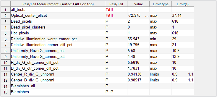 Key Blemish Detect results displayed in the Pass/Fail Monitor
For SFRplus,
{
“sfrplusResults”: {
“dateRun”: “10-Apr-2012 20:22:27”,
…
“k1_3rd_order_dist_coeff”: [0.0117],
“h1_5th_order_dist_coeff”: [-0.036],
“h2_5th_order_dist_coeff”: [0.0443],
“passfail”: {
“started_at”: “2012-04-15 16:05:10”,
“part_number”: “X-1 Rocket Plane”,
“serial_number”: “46-062”,
“ended_at”: “2012-04-15 16:05:15”,
“runtime”: [4.52085684],
“all_tests_passed”: [0],
“MTF50P_ratio_min”: [0.5],
“MTF50P_ratio”: [0.7628270592],
“MTF50P_ratio_passed”: [1],
“MTF50P_CP_weighted_mean_min”: [0.13],
“MTF50P_CP_weighted_mean”: [0.132948091],
“MTF50P_CP_weighted_mean_passed”: [1],
“Rotation_degrees_max”: [1],
“Horizontal_bars_OK_min”: [1],
“Horizontal_bars_OK”: [1],
“Horizontal_bars_OK_passed”: [1],
“All_Edge_IDs_detected”: [1],
“All_Edge_IDs_detected_OK”: [1],
“All_Edge_IDs_detected_passed”: [1],
“Mirrored_chart”: [1],
“Mirrored_chart_OK”: [1],
“Mirrored_chart_passed”: [1],
“Bayer_decode”: [1],
“Bayer_decode_OK”: [1],
“Bayer_decode_passed”: [1],
“Color_expected_detected”: [1],
“Color_expected_OK”: [0],
“Color_expected_passed”: [0],
“Stepchart_expected_detected”: [1],
“Stepchart_expected_OK”: [1],
“Stepchart_expected_passed”: [1],
“Rotation_degrees”: [-0.6021933244],
“Rotation_degrees_passed”: [1],
“FOV_degrees_diagonal_min”: [62],
“FOV_degrees_diagonal”: [103.8954245],
“FOV_passed”: [1],
“Convergence_angle_max”: [5],
“Convergence_angle_degrees_horz”: [-1.816256865],
“Convergence_angle_degrees_vert”: [-4.310448164],
“Convergence_angle_passed”: [1],
“Secondary_readout_1_center_mean_min”: [0.2],
“Secondary_readout_1_center_name”: “MTF @ .25 LP/mm”,
“Secondary_readout_1_center_mean”: [0.1525933797],
“Secondary_readout_1_center_mean_passed”: [0],
“Secondary_readout_1_outer_mean_min”: [0.2],
“Secondary_readout_1_outer_name”: “MTF @ .25 LP/mm”,
“Secondary_readout_1_outer_mean”: [0.1827151453],
“Secondary_readout_1_outer_mean_passed”: [0],
“Secondary_readout_2_center_mean_min”: [0.2],
“Secondary_readout_2_center_name”: “MTF @ .125 LP/mm”,
“Secondary_readout_2_center_mean”: [0.5577878056],
“Secondary_readout_2_center_mean_passed”: [1],
“Secondary_readout_2_outer_mean_min”: [0.2],
“Secondary_readout_2_outer_name”: “MTF @ .125 LP/mm”,
“Secondary_readout_2_outer_mean”: [0.5271610521],
“Secondary_readout_2_outer_mean_passed”: [1]
}
}
}