Deprecated in Current Release
| Requirements | Software operation | Defining Calibration Tasks | Definitions and Theory |
|---|---|---|---|
Defining and communicating coordinate systems between relevant parties is key to the successful usage of a calibrated camera. Different parties may have a more natural coordinate system (and units) for them to work in. Some of these definitions may seem trivial, however not explicitly communicating intent to all relevant parties will lead to geometrically calibrated systems not behaving as expected.
2D Image Coordinate Systems
Coordinate Axis Order
The coordinate axis order is which coordinate is first in an ordered pair. Imatest coordinates are (x, y) pairs. (y, x) pairs are not implemented in Imatest geometric calibration.
Reference Index
The reference index is the pixel location of the origin. It is related to the programing languages used and whether they are a 0 (e.g., C, C++, Java, Python) or 1 (e.g., MATLAB, Fortran) indexed language, leading to reference indices of (0, 0) or (1, 1).
Select the reference index
| INI field: count_from_one | Value: 0 | 1 |
|
Set to 0 to use (0, 0) as the reference index. Set to 1 to use (1, 1) as the reference index (MATLAB notation). |
|
Image Origin
The image origin is the location of reference index within the image data. For digital imagery, the most common locations are the lower left or upper left of the image. For film, the most common location is the center of the frame.
Select the origin location
| INI field: origin_loc | Value: ul | ur | ll | lr |
|
Set which corner to use as the origin. ul: upper left, ur: upper right, ll: lower left, lr: lower right. |
|
Image Basis Vectors
The image basis vectors describe the direction of the plus-x and plus-y axis of the image coordinates. They are often related to the image origin. An image origin in the upper left will often have +y be downward whereas an image origin in the lower left will have +y be upward.
Select the image axis basis direction
| INI field: flip_image_axis | Array of x y axis Values: 0 | 1 |
|
Select if the image axis should be flipped. 0 corresponds to righward/downward and 1 corresponds to leftward/upward for the x and y axes respectively. Example: (flip the y axis so it increases upward; corresponds with setting origin_loc to ll) flip_image_axis = 0 1 |
|
Integer Index Location
The integer index location describes the location within a pixel where the integer-valued index is within the pixel. Imatest uses the center of the pixel as the integer index location. For example the pixel at location (143, 780) will extend from 142.5 to 143.5 in x and 779.5 to 780.5 in y. The corners of a pixel may be used as an integer index location for other systems. These are not implemented in imatest.
3D World Coordinate Systems
The standard world coordinate system in the Geometric Calibration Module is shown here:
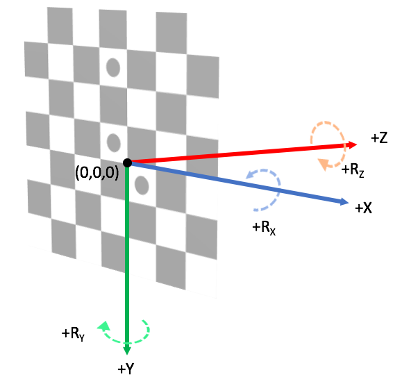
Default Imatest world coordinate system. The target center is the origin of the world. Positive-X is “chart right”, positive-Y is “chart down”, and positive-Z is “towards front of chart” (a typical camera pointing direction).
Notes:
- The origin of the World is the checkerboard intersection identified as the chart center.
- This is a right-handed coordinate system.
- The positive Z-axis is indicative of the direction a camera would be facing when pointed normal to the checkerboard.
- The positive Y-axis is downward to evoke the downward-positive image y-axis which is standard for raster-order images (and also to keep the coordinate system right-handed).
Points and objects in 3D are manipulated by rotation and translation matrices. Cameras are described by a pose (not a transformation of points). The camera center in the pinhole model is the location of the entrance aperture of the physical camera.
Coordinate Axis Order
The coordinate axis order is which coordinate is first in an ordered pair. Imatest coordinates are \((X, Y, Z)\) triplets. Triplets in other orders are not implemented in Imatest.
Axis Handedness
Imatest uses a right-handed definition of rotation. The handedness of rotations may be changed by modifying the flip_world_axis INI field
Select the world axis handedness
| INI field: flip_world_axis | Array of X Y Z axis Values: 0 | 1 |
|
Select if the image axis should be flipped. 0 corresponds to right-handed and 1 corresponds to left-handed for the X, Y, and Z axes respectively. Example: flip_world_axis = 0 0 0 |
|