Deprecated in Current Release
| Requirements | Software operation | Defining Calibration Tasks | Definitions and Theory |
|---|---|---|---|
A Test Capture relates information about what target was captured, in which images, and where from.
It can be thought of almost synonymously with a “test position” in that it relates image files to a device-to-target physical relationship (e.g. from 1m away). Importantly, a Test Capture conveys information about this relationship as it was measured from the physical test setup- depending on the accuracy of this measurement it may not be the position estimated by the calibration calculations.
Target captured
Supported values: Calibration Target definition
Information about the calibration target the test images are of must be provided.
Note: The target’s center/origin is used as the world coordinate system origin for declaring the device pose, described below.
Test Images
Supported values: list of Test Image definitions
The Test Capture keeps a list of the images captured while the camera system was at the given position. Not every device in the system needs to have an image captured at every position.
Device Pose
An initial estimate of the positioning of the device relative to the target must be provided. Note that the following forms are a pose definition in the target’s coordinate system.
You can define the pose of the reference device of the camera system (with respect to the target’s coordinate system) either by supplying a single Test Distance value, which make some further assumptions, or by supplying a full Rotation matrix and Position vector.
All distances and positions refer to the location of the reference device’s entrance pupil, not the lens front or focal plane.
Both methods require an additional distance units input to indicate the SI the units all distance values are in.
If both Position and Rotation are provided, they are used by the calibrator. If either is not provided, the Test Distance value is used.
Test Distance
Supported values: scalar value
When used, this field indicates that the reference device is positioned on the normal of the plane of the checkerboard target, directly out from the center defined by the fiducials, with no rotation, as illustrated in Figure 1.
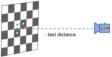
Figure 1, supplying a Test Distance
or
Rotation and Position
Rotation supported values: 3×3 matrix
Position supported values: 3-vector
Full translation vector and rotation matrix provided to indicate position anywhere in space relative to target and/or at any rotation, as illustrated in Figure 2. The reference device is The 3×3 matrix must be a valid rotation matrix (i.e., all eigenvalues are 1).
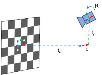
Figure 2, supplying Position (vector t) and Rotation (matrix R)
Distance Error
Supported values: scalar value
Estimated error in the spatial measurement value provided by either the Position or Test Distance input, in the same distance units.
This value is used for regularization during the calibration optimization. Providing a smaller error estimate here acts as a tighter constraint on the final estimated position.