Deprecated in Current Release
| Requirements | Software operation | Defining Calibration Tasks | Definitions and Theory |
|---|---|---|---|
A projective camera model describes the mathematics of transforming a world point into an image point. This is done by assuming a pinhole model of a camera. Coupled with a distortion model which characterizes the deviation from the pinhole model, it is possible to model most cameras in this method*.
A projective camera model only considers the relationship between world coordinates and image coordinates. It does not consider other factors such as Modulation Transfer Function (MTF), optical aberrations (e.g., chromatic aberrations, coma, etc.), linearity, and color reproduction, all of which can impact image quality.
Every pixel in an image has a coordinate \( {\mathbf{x}}_{i}^{j} = \begin{bmatrix} {x}_{i}^{j} & {y}_{i}^{j} \\ \end{bmatrix}^\top \), where \(i\) corresponds to the \(i\)th world point \( \mathbf{X}_{i} = \begin{bmatrix} {X}_{i} & {Y}_{i} & {Z}_{i} \\ \end{bmatrix}^\top \) as viewed by the \(j\)th camera (or instantiation of a camera). The projective camera model takes 3-D coordinates world coordinates and converts them into 2-D image coordinates.
\( {\mathbf{x}}_{i}^{j} = \mathcal{F}^j\left(\mathbf{X}_{i}\right)\)
There are three components to apply a projective transform model: the extrinsics, a pinhole model of the camera, and a distortion of points to account for the difference between the as-built camera and the pinhole model.
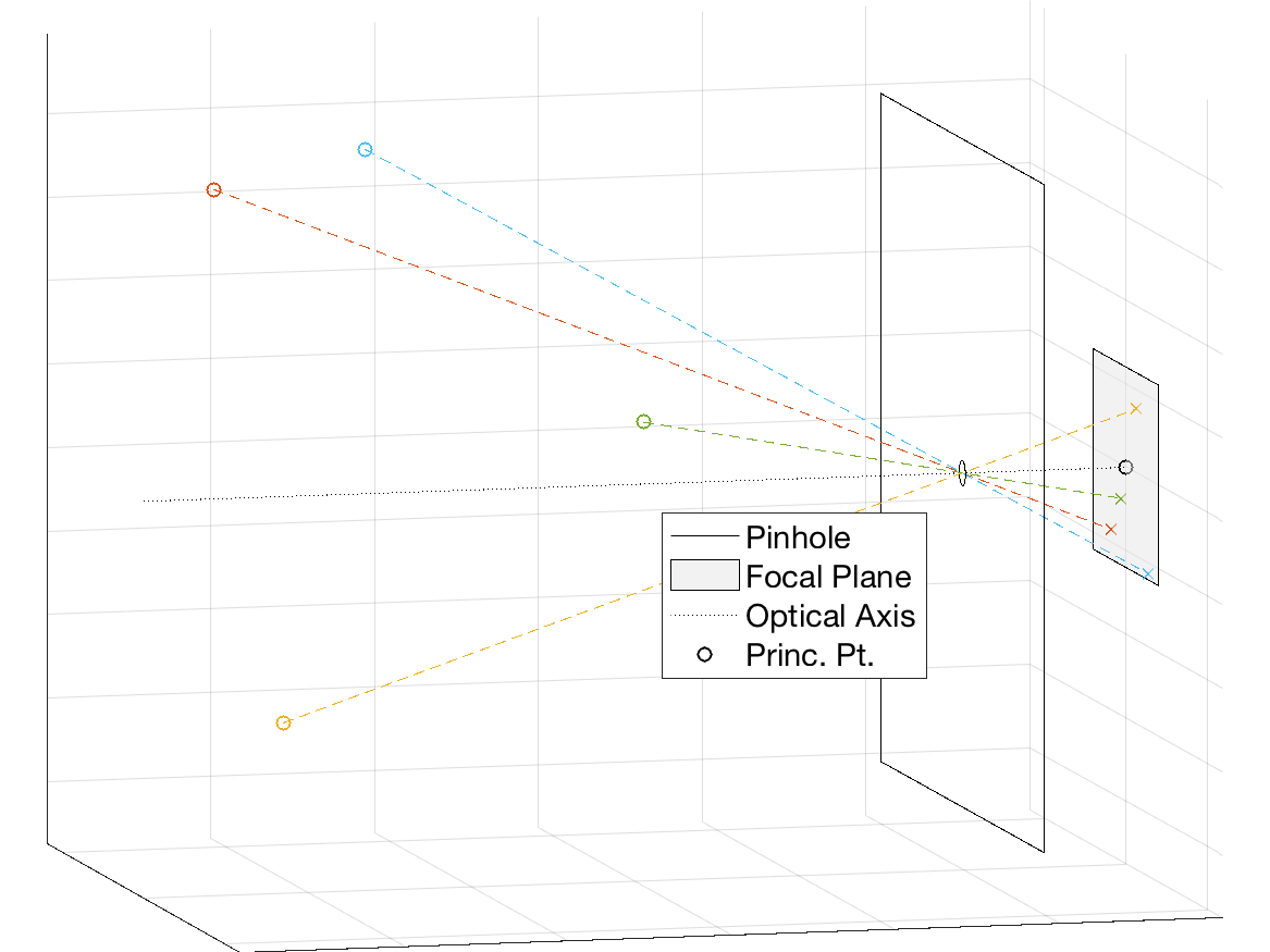
Projection of 3-D points in a pinhole camera model.

Image of projected points.
Camera Intrinsics
Camera intrinsics describe the properties of the pinhole camera model that relate camera-relative world coordinates relative to the camera into image coordinates. In the pinhole model, rays travel a straight line from an object in the scene through a pinhole to a focal plane. The geometry of this is that of similar triangles relating world coordinates to image coordinates. The mathematical model for this uses 5 parameters: focal length in the x and y directions, principle point in the x and y directions, and skew between the x and y directions.
Parameters
Focal Length
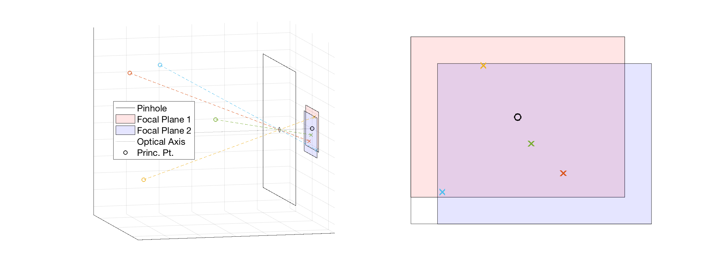
In the pinhole, model, the focal length, \(f\) is the distance from the pinhole to the focal plane along the optical axis. Systems with larger focal lengths will have more magnification over a narrower field of view (FOV), whereas smaller focal lengths will have larger coverage.
It is possible to have a different focal length along each direction of the focal plane. In this case the \(y\)-axis focal length is modified by \(\alpha\).
\(f_y=\alpha\cdot f\)
For a true pinhole camera, \(f_x=f_y\) (\(\alpha=1\)), however in practice they may due to factor including manufacturing defects, lens distortion, and images produced from a scanning system. The interpretation of non-equal focal lengths is the effective pixel shape is not square.
Principle Point
The point \((pp_x, pp_y)\) is the principle point which is the pixel coordinate of the intersection of the optical axis with the focal plane. The shift functionality of a tilt-shift translates the focal plane (and principle point) about the optical axis.
Skew
The skew factor, \( s \) introduces a shear transformation of the image. It is 0 for many cameras. Cases where it is non-zero include taking a picture of a picture (introducing a homography) and non-synchronisation of the pixel sampling process from a frame grabber. A non-zero skew implies that the x and y axis of the camera are not perpendicular to each other.
Intrinsic Matrix
The intrinsic matrix, \(\mathbf{K}\) is an upper-triangular matrix that transforms a world coordinate relative to the camera into a homogeneous image coordinate. There are two general and equivalent forms of the intrinsic matrix:
\(\mathbf{K}=\begin{bmatrix} f & s & pp_x \\ 0 & f\cdot\alpha & pp_y \\ 0 & 0 & 1\end{bmatrix}\)
\(\mathbf{K}=\begin{bmatrix} f_x & s & pp_x \\ 0 & f_y & pp_y \\ 0 & 0 & 1\end{bmatrix}\)
Many cameras may be represented with a simpler intrinsic matrix. If the skew is 0:
\(\mathbf{K}=\begin{bmatrix} f_x & 0 & pp_x \\ 0 & f_y & pp_y \\ 0 & 0 & 1\end{bmatrix}\)
If the skew is 0 and \(\alpha=1\):
\(\mathbf{K}=\begin{bmatrix} f & 0 & pp_x \\ 0 & f & pp_y \\ 0 & 0 & 1\end{bmatrix}\)
The intrinsic matrix of the \(j\)th camera is applied to the \(i\)th camera-relative 3D point to produce a homogeneous image point.
\(\begin{bmatrix} {x}_{i}^{j} \\ {y}_{i}^{j} \\{w}_{i}^{j} \end{bmatrix}=\mathbf{K}^j\begin{bmatrix} {X}_{i} \\ {Y}_{i}\\{Z}_i \end{bmatrix}\)
Sample Calculation
Let \(\begin{bmatrix}X&Y&Z\end{bmatrix}^\top\) be a point relative to the camera. We will assume a
\(\begin{bmatrix}x\\y\\w\end{bmatrix}=\begin{bmatrix} f & 0 & pp_x \\ 0 & f & pp_y \\ 0 & 0 & 1\end{bmatrix}\begin{bmatrix}X\\Y\\Z\end{bmatrix}\)
\(\begin{bmatrix}x\\y\\w\end{bmatrix}=\begin{bmatrix} f \cdot X + pp_x \cdot Z \\ f \cdot Y + pp_y \cdot Z\\Z\end{bmatrix}\)
After converting to inhomogeneous coordinates
\(\begin{bmatrix}x’\\y’\end{bmatrix}=\begin{bmatrix} \displaystyle\frac{f \cdot X + pp_x \cdot Z}{Z} \\ \displaystyle\frac{f \cdot Y + pp_y \cdot Z}{Z}\end{bmatrix}=\begin{bmatrix} f \cdot \displaystyle\frac{X}{Z} + pp_x \\ f \cdot \displaystyle\frac{Y}{Z} + pp_y\end{bmatrix}\)
Inspection of this result shows that the distance from the optical axis (principle point) is proportional to the ratio of the world points distance from the optical axis to the distance to the camera. This means that a point that is twice as far from the optical axis and twice as far from the camera will map to the same image point. From a single camera, the best reconstruction of a point that can be done is that the point lies somewhere on a line.
Units
All of these values are calculated in units of number of pixels. The pixel pitch, \(p\), is used to convert between number of pixels and physical units. For example:
\(f [\mathrm{mm}]=f [\mathrm{pixels}] \cdot p \left[\frac{\mu\mathrm{m}}{\mathrm{pixel}}\right] \cdot \frac{1 [\mathrm{mm}]}{1000 [\mu \mathrm{m}]}\)
Inverse
The inverse of the camera intrinsic matrix is used to transform undistorted image points into lines from the camera center.
The inverse of the two general forms of the intrinsic matrix are given by:
\(\mathbf{K}^{-1}=\displaystyle\frac{1}{f^2\cdot \alpha}\begin{bmatrix} f\cdot\alpha & -s &pp_y\cdot s-pp_x\cdot f\cdot\alpha \\ 0 & f & -pp_y\cdot f \\ 0 & 0 &f^2\cdot \alpha\end{bmatrix}=\displaystyle\frac{1}{f_x\cdot f_y}\begin{bmatrix} f_y & -s & pp_y\cdot s-pp_x \cdot f_y\\ 0 & f_x & -pp_y\cdot f_x \\ 0 & 0 & f_x\cdot f_y\end{bmatrix}\)
The inverse for the zero skew case is:
\(\mathbf{K}^{-1}=\displaystyle\frac{1}{f_x\cdot f_y}\begin{bmatrix} f_y & 0 & -pp_x\cdot f_y \\ 0 & f_x & -pp_y\cdot f_x \\ 0 & 0 & f_x\cdot f_y\end{bmatrix}=\displaystyle\frac{1}{f^2\cdot \alpha}\begin{bmatrix} f\cdot\alpha & 0 & -pp_x\cdot f\cdot\alpha \\ 0 & f & -pp_y\cdot f \\ 0 & 0 & f^2\cdot\alpha\end{bmatrix}\)
The inverse for the \(\alpha=1\) case is:
\(\mathbf{K}^{-1}=\displaystyle\frac{1}{f^2}\begin{bmatrix} f & -s & pp_y\cdot s-pp_x\cdot f \\ 0 &f & -pp_y\cdot f \\ 0 & 0 & f^2\end{bmatrix}\)
The inverse for the zero skew and \(\alpha=1\) case is:
\(\mathbf{K}^{-1}=\displaystyle\frac{1}{f}\begin{bmatrix} 1 & 0 & -pp_x \\ 0 & 1 & -pp_y \\ 0 & 0 & f\end{bmatrix}\)
Distortion
A camera’s distortion model describes the deviation of a physical camera from the projective camera model. It transforms undistorted 2D image points into distorted 2D image points (the ones off of the camera). The inverse distortion model transforms distorted image points into undistorted ones.
Camera Extrinsics
The camera extrinsics describe the position and orientation of a camera in the world. There are two ways of describing the coordinate transform between world and camera-relative coordinates: a point transformation and an axes transformation (pose). They both that the same form of a rotation/translation matrix and are the inverse of each other.
The camera’s center corresponds to the location of the entrance pupil of the camera. In panoramic photography, this is often called the no-parallax point. Cameras with a large field of view (e.g., fish-eye cameras) will have different entrance pupil locations at different field angles. For these cameras, the on-axis entrance pupil location is used.
Point Transformation
The point transformation description transforms a world point into a camera-relative point. Its rotation/translation matrix is directly right multiplied to intrinsics matrix to form the camera matrix.
\(\begin{bmatrix}x\\y\\w\end{bmatrix}=\left[\begin{array}{ccc}&&\\&\mathbf{K}&\\&&\end{array}\right]\left[\begin{array}{ccc|c}&&&\\&\mathbf{R}&&\mathbf{t}\\&&&\end{array}\right]\begin{bmatrix}X\\Y\\Z\\1\end{bmatrix}\)
In point transformation notation, the camera is located at \(-\mathbf{R}^\top\mathbf{t}\).
Axes Transformation
The axes transformation is also known as a pose. The camera’s pose (extrinsics) describe the relative position and orientation of the camera. The inverse of the pose rotation/translation matrix is right multiplied to intrinsics matrix to form the camera matrix.
\(\begin{bmatrix}x\\y\\w\end{bmatrix}=\left[\begin{array}{ccc}&&\\&\mathbf{K}&\\&&\end{array}\right]\left[\begin{array}{ccc|c}&&&\\&\mathbf{R}&&\mathbf{t}\\&&&\end{array}\right]^{-1}\begin{bmatrix}X\\Y\\Z\\1\end{bmatrix}\)
\(\begin{bmatrix}x\\y\\w\end{bmatrix}=\left[\begin{array}{ccc}&&\\&\mathbf{K}&\\&&\end{array}\right]\left[\begin{array}{ccc|c}&&&\\&\mathbf{R}^{\top}&&-\mathbf{R}^{\top}\mathbf{t}\\&&&\end{array}\right]\begin{bmatrix}X\\Y\\Z\\1\end{bmatrix}\)
In camera pose notation, the camera center is located at \(\mathbf{t}\).
Camera Matrix
The camera matrix, \(\mathbf{P}\), is the combination of camera intrinsic matrix and the point transform.
\(\mathbf{P}=\left[\begin{array}{ccc}&&\\&\mathbf{K}&\\&&\end{array}\right]\left[\begin{array}{ccc|c}&&&\\&\mathbf{R}&&\mathbf{t}\\&&&\end{array}\right]\)
The camera matrix transforms world points into homogeneous image coordinates.
End-to-end
World Points to Image Points
- Transform a world coordinate into a camera-relative coordinate by multiplying by the world point to image point transform. This transform is the inverse of the pose.
- Apply the intrinsic camera matrix to the camera-relative coordinate to produce a homogeneous image coordinate.
- Convert the homogeneous image coordinate into an inhomogeneous coordinate.
- Apply the distortion model to identify the location of the image of the world point on the focal plane.
Point Transform Notation
\(\begin{bmatrix}x\\y\\w\end{bmatrix}=\underbrace{\left[\begin{array}{ccc}&&\\&\mathbf{K}&\\&&\end{array}\right]}_{\mathrm{intrinics}}\underbrace{\left[\begin{array}{ccc|c}&&&\\&\mathbf{R}&&\mathbf{t}\\&&&\end{array}\right]}_{\mathrm{inverse\ pose}}\begin{bmatrix}X\\Y\\Z\\1\end{bmatrix}\)
\(\begin{bmatrix}x’\\y’\end{bmatrix}=\begin{bmatrix}\mathrm{distort}_{x}\!\!\left(\displaystyle\frac{x}{w}\right) \\\mathrm{distort}_{y}\!\!\left(\displaystyle\frac{y}{w}\right)\end{bmatrix}\)
Axes Transform Notation
\(\begin{bmatrix}x\\y\\w\end{bmatrix}=\underbrace{\left[\begin{array}{ccc}&&\\&\mathbf{K}&\\&&\end{array}\right]}_{\mathrm{intrinics}}\underbrace{\left[\begin{array}{ccc|c}&&&\\&\mathbf{R}^{\top}&&-\mathbf{R}^{\top}\mathbf{t}\\&&&\end{array}\right]}_{\mathrm{inverse\ pose}}\begin{bmatrix}X\\Y\\Z\\1\end{bmatrix}\)
\(\begin{bmatrix}x’\\y’\end{bmatrix}=\begin{bmatrix}\mathrm{distort}_{x}\!\!\left(\displaystyle\frac{x}{w}\right) \\\mathrm{distort}_{y}\!\!\left(\displaystyle\frac{y}{w}\right)\end{bmatrix}\)
Image Points to Lines
- Apply the inverse distortion model to undistort the image points. This puts them into a pinhole camera geometry.
- Transform the image coordinate to a homogeneous coordinate with weight \(w\). Any real, non-zero \(w\) may be used, however two common ones are 1 or the distance from the camera center to the world point.
- Multiply the homogeneous image coordinate by the inverse of the intrinsic camera matrix. This vector is the direction vector of the line between the point and the camera center in camera-relative coordinates.
- Apply the rotation of the camera’s pose (inverse of the point transform matrix) to the direction vector. Separately, compute the camera center to form a point on the 3D line.
Point Transform Notation
\(\begin{bmatrix}X\\Y\\Z\end{bmatrix}=w\cdot\underbrace{\begin{bmatrix}&&\\&\mathbf{R}^{\top}&\\&&\end{bmatrix}\begin{bmatrix}&&\\&\mathbf{K}^{-1}&\\&&\end{bmatrix}\begin{bmatrix}\mathrm{undistort}_x(x’) \\\mathrm{undistort}_y(y’)\\1\end{bmatrix}}_{\mathrm{ray\, direction}}\underbrace{-\begin{bmatrix}&&\\&\mathbf{R}^{-1}&\\&&\end{bmatrix}\begin{bmatrix} \\ \mathbf{t} \\\phantom{} \end{bmatrix}}_{\mathrm{camera\, center}}\)
where \(w\cdot\left|\left|\begin{bmatrix}\mathrm{undistort}_x(x’) & \mathrm{undistort}_y(y’) & 1\end{bmatrix}^\top\right|\right|\) is the distance from the camera center (location of the entrance pupil) to the world point.
Axes Transform Notation
\(\begin{bmatrix}X\\Y\\Z\end{bmatrix}=w\cdot\underbrace{\begin{bmatrix}&&\\&\mathbf{R}&\\&&\end{bmatrix}\begin{bmatrix}&&\\&\mathbf{K}^{-1}&\\&&\end{bmatrix}\begin{bmatrix}\mathrm{undistort}_x(x’) \\\mathrm{undistort}_y(y’)\\1\end{bmatrix}}_{\mathrm{ray\, direction}}+\underbrace{\begin{bmatrix} \\ \mathbf{t} \\\phantom{} \end{bmatrix}}_{\mathrm{camera\, center}}\)
where \(w\cdot\left|\left|\begin{bmatrix}\mathrm{undistort}_x(x’) & \mathrm{undistort}_y(y’) & 1\end{bmatrix}^\top\right|\right|\) is the distance from the camera center (location of the entrance pupil) to the world point.