by Henry Koren, inspired by Paul Romanczyk, edited by Norman Koren
Not all MTF measurement systems will necessarily provide the same results. The quality of the test target can impact the measurements you obtain. Long distance tests are ideally performed at the hyperfocal distance, where there is enough depth of field to have acceptable focus at infinity. Long-range tests which exceed the available space within your lab or factory are the most challenging. A collimator or relay lens system can be used to produce virtual targets at a simulated distance. The measurements obtained through a collimator can diverge from measurements obtained from free-space test targets. This article will discuss how to cope with that.
Reflective collimators, such as ones which include off-axis parabolic mirrors, can offer no MTF loss but are not compact. Refractive collimators offer compact form factors, but like all lenses, are not as sharp in the outer portions of the lens as they are in the center. Since this is less of a problem with narrow field of view collimators, one approach is to have an array of narrow collimators aligned in a “star field” in order to cover a sufficient portion of your lens. Or you can use a single collimator, and tilt and rotate the camera relative to the collimator in order to measure the necessary points across your image. These approaches are complex, more difficult to align and could be prohibitively costly or time-consuming.
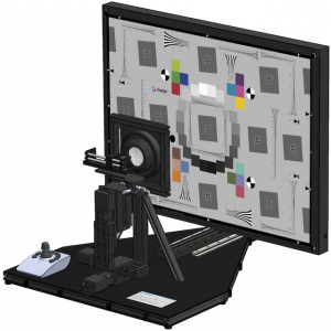
Imatest’s collimator fixture provides a simpler and more cost-effective alternative which seeks to fill most of your field of view, up to 120°, with a single intermediate optic. The disadvantage of this approach is that there could be some MTF loss from the chart and collimator which will impact the reliability of these results.
To adjust for this, one can either (A) try to correct for the degradation of collimator MTF measurements, or (B) adjust the expectations for MTF results.
A set of reference devices can be used to correlate free-space measurements to collimator measurements. A “golden sample”, or a device that is as perfect as can be, could be used to understand the upper bound for the range of key performance indicators (KPI) that you are looking to validate. However, this sample may be cherry-picked and may not be representative of an average or marginally acceptable component or device coming off the line. The difference depends on the precision tolerancing of your lens manufacturing and active alignment processes. If the golden sample is much better than your chosen pass/fail threshold, the MTF loss it experiences from the collimator+chart might be proportionally greater than it would be to a more ordinary device. Reliance on golden samples could lead to overly reduced pass/fail thresholds which could allow sub-standard devices to pass, but this may be appropriate during the Prototype or design validation testing (DVT) phases.
A superior approach is to use “bronze samples” which are close to the thresholds of acceptability. These devices can be fully characterized in a free-space lab which does not have any MTF loss due to chart or collimator. Then the samples can be moved to the collimator fixture. By understanding the proportionally lower MTF response on the collimator fixture, the measurements obtained in free-space can be appropriately adjusted downwards.


