|
Summary
Chart MTF compensation can double the megapixel suitability of a test chart. Results taken with different test charts will be more consistent.
|
Introduction | Calculation | MTF compensation files | Applying the compensation
Sensor MTF compensation | Chart MTF measurements
Introduction
Imatest MTF measurements are affected by both chart and camera quality. Since its inception, Imatest has recommended test charts that are large enough to minimize the effects of the chart on camera MTF measurements. Although we have some descriptions of chart quality on the Chart Quality Index, Reflective charts, and Transmissive charts quality pages, these pages don’t have enough detail to determine the precise effect of chart MTF on camera MTF measurements, which is particularly important in situations where geometric constraints (test equipment and lab size, etc.) make it difficult to meet the chart recommendations.
Convolution and deconvolution – The response of a linear system can be calculated by convolving its components. Convolution is a complex operation— as its name implies— but when response is converted into frequency domain (by means of a Fourier transform), it becomes simple multiplication. The measured response (Modulation Transfer Function = MTF) of an imaging system is the product of its elements:
\( MTF_{system-measured} = MTF_{chart-projected} \times MTF_{lens} \times MTF_{sensor} \times MTF_{image-processing}\)
MTFchart-projected (the chart MTF projected on the image sensor) is not really a part of the imaging system, so we’ve dealt with it by recommending that charts be used in conditions (low magnification) where MTFchart-projected stays close to 1 in the frequency range of interest. Since our recommendations have been conservative the results have been “good enough” in most instances.
Starting in Imatest 5.1 the effects of the chart can be reduced by dividing the measured MTF by MTFchart-projected, which is equivalent to deconvolution in the spatial domain. We can also calculate the approximate lens MTF by dividing measured MTF by a geometrical model of MTFsensor, which we use because (A) reliable measurements of MTFsensor are difficult to obtain, and (B) results are closer to lens MTF than you can get without the correction.
Chart-compensated MTF model – Chart MTF is measured in units of Cycles per Object mm from a printed edge (appropriately slanted for the measurement), then fit to a simple equation that fits a wide range of chart MTF measurements.
\(\displaystyle MTF_{chart} (f) \cong e^{-a_1 f – (a_2 f)^2}\); f in units of Cycles/Object mm.
When the chart is imaged (projected) on the sensor, the projected chart MTF is calculated by transforming the chart frequency units to the native sensor units (Cycles/Pixel) using
\(f(\text{C/Obj mm}) = f(C/P) \times \text{magnification} \times \text{pixels/mm} \)
\(MTF_{chart-projected}(f) = MTF_{chart}(f(C/P) \times \text{magnification} \times \text{pixels/mm}) = MTF_{div}(f)\)
In Imatest sharpness modules, pixels/mm is typically derived from the user-entered value of pixel pitch (in μm), where pixels/mm = 1000 / (pixel pitch (μm)). Magnification is either entered in the settings window or derived from geometrical factors (like the bar-to-bar spacing in SFRplus or the vertical registration mark spacing in eSFR ISO). We use MTFdiv(f) and MTFchart-projected(f) interchangeably because the measured camera MTF (MTFmeasured) is divided by MTFdiv to obtain the compensated (more accurate) measurement.
If MTFdiv at the Nyquist frequency (fNyq = 0.5 C/P) is lower than 0.9 (90%), measurement accuracy can be improved by dividing the measured MTF by MTFdiv. If MTFdiv(fNyq) is greater than 0.9, there is very little improvement.
\(\displaystyle MTF_{chart-compensated}(f) =\frac{ MTF_{measured}(f)}{MTF_{div}(f)}\)
The actual calculation (details below) is performed with files that contain parametric fits to the measured data for the specific media type and printing technology. Applying chart compensation will improve the consistency of MTF measurements taken on different test charts.
Lens MTF measurements – Imatest traditionally measures the MTF of the entire system, lens + sensor + image processing, but a number of customers are interested in measuring the MTF of the lens alone. To do so, the effects of the sensor and image processing must be removed. It’s easy to minimize image processing by converting files from raw using LibRaw (for commercial files) or Generalized Read Raw (for binary files), but removing the effects of the image sensor is more difficult. Although exact measurements of sensor MTF are difficult to come by (as of early 2018) we can get a reasonable approximation for many situations (visible light, moderate pixel size) using a simple theoretical equation for geometrical sensor MTF:
\(\displaystyle MTF_{sensor} =\frac{ \sin \frac{\pi f}{2 f_{Nyq}}}{ \frac{\pi f}{2 f_{Nyq}}} = \text{sinc} \frac{\pi f}{2 f_{Nyq}}\) where fNyq = Nyquist frequency = 1/(2 pixel pitch).
For this equation to be valid the sensor must not have an anti-aliasing filter (OLPF) and a raw image must be used (converted with LibRaw or Read Raw). JPEG images from cameras inevitably have signal processing (sharpening and noise reduction) that throws off the results. This approximation is reasonably good for visible light, but poorer for Near Infrared (NIR), where electron diffusion in the silicon degrades the MTF.
Chart-compensated MTF calculation
Starting with Imatest 5.1 you can compensate MTF measurements for chart sharpness. Compensation is available in all slanted-edge modules (SFR, SFRplus, eSFR ISO, SFRreg, and Checkerboard), and for Star, Random (Dead Leaves, Spilled coins, etc.), and Log F-Contrast. Applying chart compensation requires care.
Summary of operations
- Read the image, then press the Chart MTF compensation button in the settings window.
- Check the Apply chart MTF compensation checkbox,
- Read a file that contains a model of the chart MTF (each specific chart medium has a model).
- Enter the sensor pixel spacing (typically in microns) and either the magnification or the parameters that can be used to calculate magnification (for example, the bar-to-bar spacing in SFRplus).
- Run the analysis as usual. The settings will be saved for the individual module.
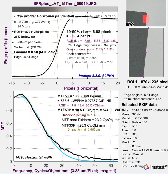
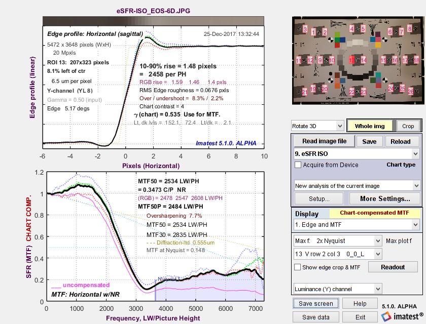 Chart-compensated Edge MTF plot. Uncompensated MTF shown in magenta ____.
Chart MTF compensation files
Click on a link in the table to download the chart compensation file for the indicated media type. Save the file to any convenient location. (We recommend the Imatest Resources folder, which can be located by pressing Open resources folder in the Chart and sensor MTF compensation or Options II menu.) Although the files contain several lines, only the numbers in the first line (the first line of Key values in the table below) are used for chart compensation. The remaining lines contain annotations (the file used for the calculation, the chart MTF50, etc.) Some of the data is relatively old: we will be taking new measurements.
| Media | Link | Key values* |
| B&W Photographic film (LVT process) |
BW_LVT_film_MTF_compensation.csv | -0.00942, -0.04480 MTF50 = 20.8 C/Obj mm |
| Color Photographic film (LVT process) |
Color_LVT_film_MTF_compensation.csv | -0.00968, 0.04781 MTF50 = 18.2 C/Obj mm |
| Inkjet: Displaytrans transparency |
DisplayTrans_4-1_compensation.csv | 0.02733, 0.20737 MTF50 = 3.56 C/Obj mm |
| Inkjet: Epson Matte | Enhanced_Matte_precision_MTF_compensation.csv | 0.01998, 0.24561 MTF50 = 3.22 C/Obj mm |
| Inkjet: Epson Hot Press Bright |
Epson_Hot_Press_Bright_BW_MTF_compensation.csv | 0.08608, 0.13545 MTF50 = 3.0 C/Obj mm |
| B&W Photographic paper | Photo_Paper_MTF_compensation.csv | 0.10603, 0.00001 MTF50 6.44 C/Obj mm |
*The first key value line contains all information required for the Chart Compensation file. The second line (MTF50 in Cycles/Object mm) is included for reference— for conveniently comparing chart sharpness.
We plan to supply MTF compensation files in Imatest builds. They will also be available for downloading in the Reflective charts and Transmissive charts quality pages.
You can create an MTF compensation file using the technique described below in Appendix: Chart MTF measurement. This file should be saved with a descriptive name to any convenient location (though we recommend the Resources folder).
Applying MTF compensation
-
Read the image in one of the sharpness modules that supports chart compensation.
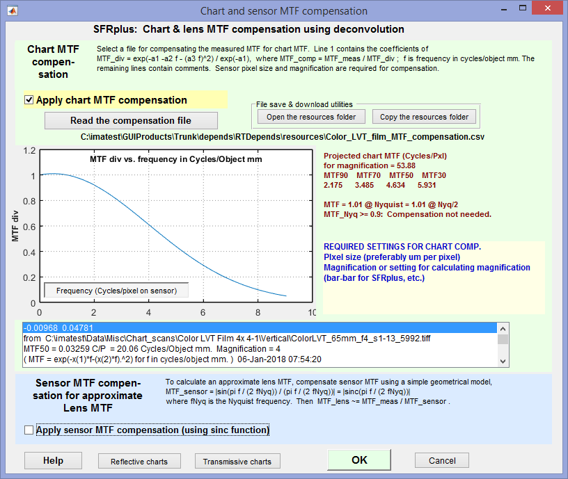
MTF compensation window, showing chart MTF for a color LVT chart
- In the Settings window (the More settings window in Rescharts slanted-edge modules), Enter the sensor pixel spacing (typically in microns) and either the magnification or the parameters that can be used to calculate magnification (for example, the bar-to-bar spacing in SFRplus or the vertical registration mark spacing in eSFR ISO).
- Press the Chart MTF compensation button ( MTF compensation in Rescharts slanted-edge modules). This opens the window shown on the right.
- If a file has been read (and stored) a plot like the one on the right will be displayed. If not, press the Read the compensation file button and select the appropriate compensation file for the test chart media.
- Check the Apply chart MTF compensation checkbox.
- Click OK.
- Run the analysis as usual. The settings will be saved for the individual module.
Chart compensation will increase MTF. It will be indicated in several places.
- in plot titles (in many cases),
- in the y-label of MTF plots, which will typically change from MTF to MTF CHART COMPENSATED (or MTF CHART_COMP. if space is tight),
- In Rescharts, Chart or lens MTF comp. will appear on the right of the window.
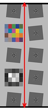
Chart measurements for calculating magnificationSFRplus: Bar-to-bar height (top of top bar to bottom of bottom bar) in cm. eSFR ISO: Registration mark vertical spacing in cm. Checkerboard: Square height (not shown) in cm. For these three modules the chart should be measured carefully. The measurement is entered on the right of the Settings window. Magnification must be entered directly for all other modules.
|
 SFRplus SFRplus |
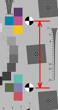 eSFR ISO eSFR ISO |
|
Things to check carefully Using chart compensation is somewhat more error-prone than not using it. You need to check settings carefully. Make sure
MTF compensation increases measured MTF values at high spatial frequencies. This often means that noise as well as the signal will be boosted. This is very visible in the above image, taken with a Canon EOS-6D DSLR, which has an anti-aliasing filter that removes most response above Nyquist (~3600 LW/PH). What is left is primarily noise. |
Effects of MTF compensation
Here is a typical example, run in Rescharts for a Star chart image. Indicators appear in the y-label, title, and on the middle-right of the Rescharts window. The compensation file name (media type) does not yet appear. Two additional curves appear on the plot. The original MTF without compensation appears as a Magenta dotted line ………..The projected MTF of the chart (MTFchart-projected ) is a cyan dotted line ………..
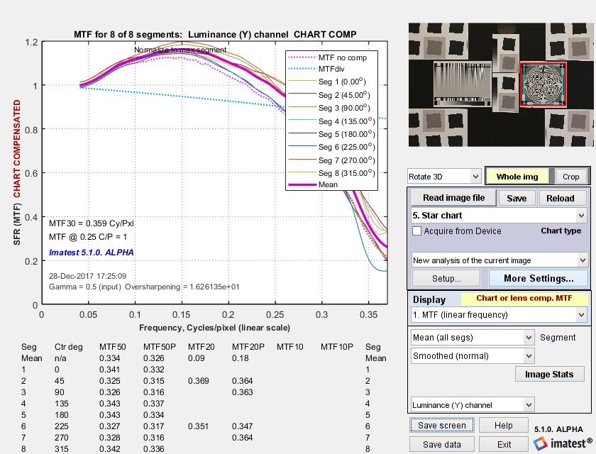 Chart MTF-compensated results for Star chart
There are a few things to watch out for when doing these measurements.
To prevent excessive noise boost MTFchart-projected (the cyan dotted line ……….) must not drop too low (to 0.3) in the frequency range of interest.
Sensor MTF compensation for approximate Lens MTF measurements
We receive frequent requests from customers who want to measure lens MTF, and it’s always disappointing to tell them Imatest measures system MTF, which includes the effects of the image sensor, and not lens MTF. While sensor MTF can be removed by deconvolution, i.e., the same division process (in frequency domain) used to compensate for the chart MTF, reliable sensor MTF data is difficult to obtain. But even without exact sensor MTF data Imatest can do a partial (approximate) correction for the sensor MTF.
Sensor MTF actually consists of two or three components.
- a geometrical component derived from the pixel dimensions. Its equation is
\(\displaystyle MTF_{sensor} = \frac{\sin \bigl( \pi f / (2 f_{Nyq})\bigr) }{ \pi f / (2 f_{Nyq})} = \text{sinc} \bigl( \frac{\pi f}{2 f_{Nyq}}\bigr)\) where fNyq = Nyquist frequency = 1/(2 pixel pitch).
Note that this equation has a null at f = 2 fNyq, i.e., twice the Nyquist frequency. Sensor response at fNyq is 2/π = 0.6366.
- an electrical component caused by diffusion of light inside the silicon, resulting in crosstalk, which degrades MTF. This degradation is difficult to measure. Crosstalk is affected by sensor technology and is worse at longer (Near Infrared = NIR) wavelengths and for very small pixels. It is discussed in the Adimec page on sensor MTF.
- (not in all cameras) an anti-aliasing (AA) filter, sometimes called an Optical Low Pass Filter (OLPF), frequently found in older DSLR or mirrorless cameras with interchangeable lenses. An AA filter is typically a plastic layer mounted in front of the sensor that reduces aliasing (visible as stair-stepping or Moiré) by blurring the image. Aliasing is caused by strong response above fNyq with sharp lenses. Nikon has a nice article comparing the performance of similar cameras with and without AA filters. AA filters are true wildcards in their effect on sensor MTF response— we have never seen a response curve or equation for AA filter response. All we can say is that they significantly reduce response above and have some effect on response below fNyq.
Imatest can correct for the geometrical component of lens MTF in cameras without anti-aliasing filters. Before you apply this correction, you should find out if your camera has one. Most DSLR and mirrorless interchangeable cameras made before 2015 have them. Since 2015 a number of cameras have small enough pixels (sufficient megapixels) to dispense with them with minimal risk of Moiré. Since removing the AA filter significantly improves camera sharpness (beyond the simple megapixel increase) it may be mentioned in the camera specifications and in reviews. For example, see Wired’s review of the Panasonic GX85.
To apply the lens MTF correction, check the Apply sensor MTF compensation checkbox in the compensation window, shown above.
|
These results should not be represented as true lens MTF. At best it’s approximate— closer to true lens MTF than measurements made without the correction, but definitely not all the way there. Sensor MTF compensation should only be applied to cameras without anti-aliasing filters. |
A recent reference to sensor MTF is Interferometric Measurement of Sensor MTF and Crosstalk (2017) by T. Georgiev, et. al. of Qualcomm, presented at the Electronic Imaging 2017 conference. They used a Ximea MQ013RG-E2 sensor, which has 5.3μm pixels.
Adimec has a page, CCD vs. CMOS – Modulation Transfer Function (MTF) in NIR, that explains why Sensor MTF is generally worse than the theoretical sinc(πf/(2 fNyq)) model, especially for small pixels and Near Infrared (NIR) wavelengths (> 700μm). It has a plot of MTF at the Nyquist frequency vs. wavelength for two Sony sensors with relatively large pixels, the ICX674 (4.54μm pixels) and IMX174 (5.86μm pixels). MTF is relatively constant and close to the theoretical value of 0.6366 below 700 nm. The method used to obtain this plot is not stated.
Appendix. Chart MTF measurementMost users won’t be measuring chart quality themselves. They’ll use the measurement results in Chart MTF compensation files provided by Imatest in the above links. Those users can skip this section. 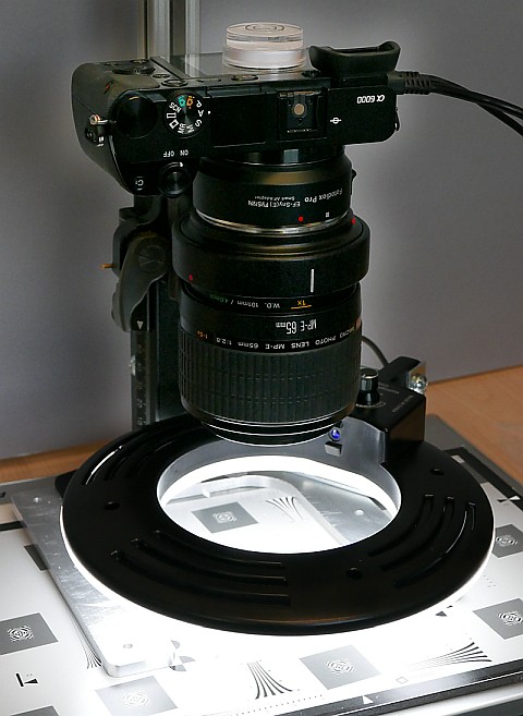 Imatest setup for measuring test chart sharpness Chart MTF is measured from images of slanted-edges on various media (inkjet paper, photographic paper, B&W or color film, or Chrome on Glass) at the same contrast (usually 4:1 or 10:1) used for testing lenses. These media are both transmissive and reflective and have a wide range of sharpness.
\(MTF_{chart-projected}(f) = MTF_{chart}(f(C/P) \times \text{magnification} \times \text{pixels/mm})\) Pixels/mm is derived from the pixel pitch (μm per pixel), which is entered in the settings window. \(\text{pixels/mm} = 1000 / \text{pixel pitch (um/pixel)}\) The equation for the compensated MTF is \(\displaystyle MTF_{chart-compensated} = \frac{MTF_{measured}}{\text{max}(MTF_{chart-projected}, 0.3)}\) MTFchart-projected is also called MTFdiv because it is used to divide MTFmeasured. The minimum value of the denominator must be greater than 0.3 because smaller values are unreliable and can cause an excessive noise boost. The frequency where projected chart MTF drops to 0.3 should be outside the range of interest for the measurement— above the Nyquist frequency fNyq . |
Do you have the latest Imatest Master version?
If you do not already have Imatest Master, purchase or try a free trial of Imatest Master version 5.1 to use the MTF Compensation feature.