Stray light (flare) documentation pages
Introduction: Intro to stray light testing and normalized stray light | Outputs from Imatest stray light analysis | History
Background: Examples of stray light | Root Causes | Test overview | Test factors | Test Considerations | Glossary
Calculations: Metric image | Normalization methods | Light source mask methods | Summary Metrics | Analysis Channels | Saturation
Instructions: High-level Imatest analysis instructions (Master and IT) | Computing normalized stray light with Imatest | Motorized Gimbal instructions
Settings: Settings list and INI keys/values | Standards and Recommendations | Configuration file input
Page Contents
This page provides instructions for collecting data and using Imatest to compute normalized stray light.
- What is normalized stray light
- How to measure normalized stray light
- References
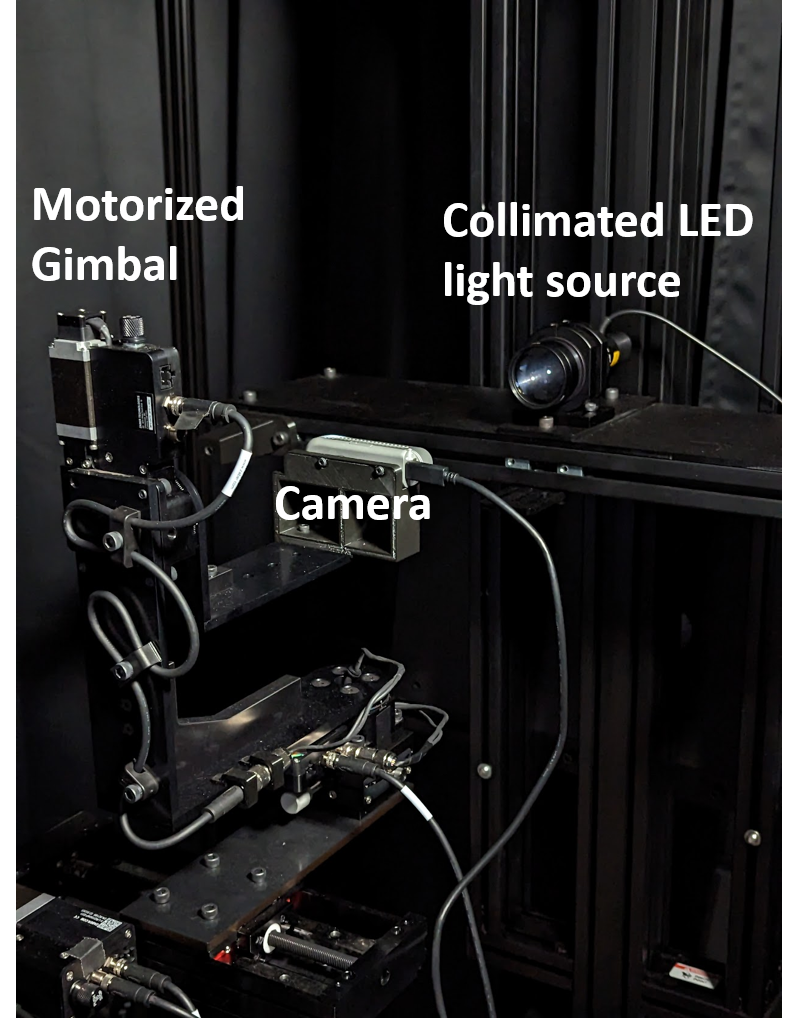
A stray light testing setup composed of a camera mounted to a two-axis rotation stage (Imatest Motorized Gimbal) with a collimated LED light source illuminating the camera. The setup is mostly black and is surrounded by blackout curtains to reduce the magnitude of unwanted reflections.
What is normalized stray light
Normalized stray light is a metric for evaluating the magnitude of stray light in an image. It measures the response from stray light in relation to the response from the on-axis direct image of the source, and is analogous to established metrics such as Point Source Rejection Ratio (PSRR) and Extended Source Rejection Ratio (ESRR) [1].
Additional background information on normalized stray light can be found here. A summary of settings needed to compute normalized stray light (and other metrics) can be found here.
How to measure normalized stray light
Measuring normalized stray light involves capturing images of a small, bright light source in a dark room. To compute normalized stray light, Imatest can be used to normalize the images under test by the level (pixel value or digital number) from the direct image of the source. The direct image of the source is the small region in the image that represents the true size of the light source (i.e., if there were no stray light or blooming in the image). However, in many cases, the direct image of the source may need to be saturated and blooming to reveal measurable stray light (flare) artifacts. To address this, a separate reference image can be captured and used, wherein the direct image of the source is not saturated by lowering the level of light on the camera sensor by a known amount [2]. This technique provides a way to normalize the image data by a factor that is not saturated. Note that the methods associated with normalized stray light assume that the data are linear and that Bunsen-Roscoe reciprocity law holds.
Additional information about normalized stray light and the test set up can be found here. A high level overview of the stray light test is provided here.
Procedure for normalized stray light data collection
- Adjust the level of light such that measurable stray light (flare) artifacts are induced in the image from the camera. Note that it may be useful to capture data with several light levels or camera integration times to better measure different magnitudes of stray light. The light level can be adjusted with one or more of the following techniques:
- Adjust the power level of the light source
- Adjust the integration time of the camera
- Adjust the gain setting of the camera (note that increased gain can induce noise)
- Measure the light level at the location of the camera (e.g., irradiance or illuminance measured using a spectroradiometer). This is the test light level.
- Capture an on-axis reference image of the light source wherein the direct image of the source is not saturated by using one or more of the following techniques:
- Attenuate the light by placing a neutral density filter in front of the source
- Lower the power level of the light source and measure the difference in light level at the location of the camera
- Use a shorter camera integration/exposure time
- Use a lower camera gain setting
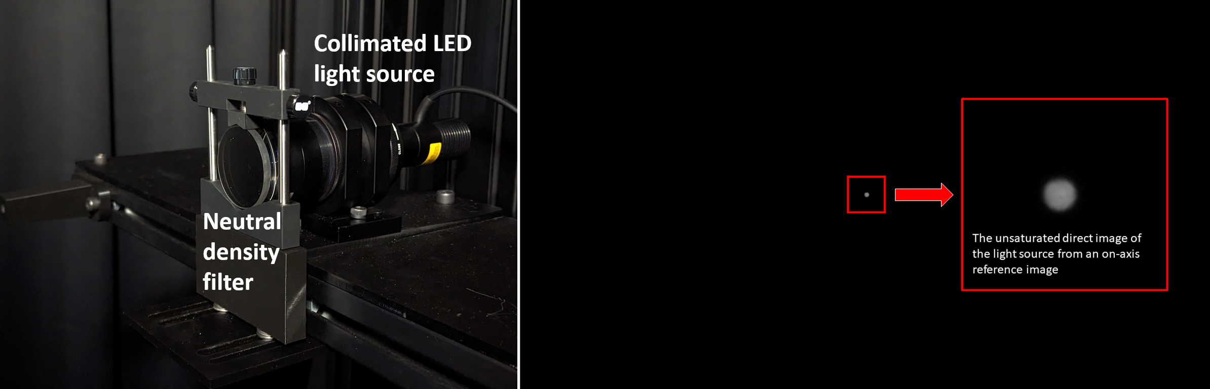
Left: A neutral density filter (ND 2.5) is placed in front of a collimated LED light source to attenuate the light for the reference image. Right: An on-axis reference image showing an unsaturated direct image of the light source.
- Adjust the level of light back to the test light level (for example, by increasing camera exposure time and/or by removing the ND filter).
- Capture test images of the light source with the source positioned at different angles in and/or outside of the camera FOV.
- Note: Comprehensive testing may require capturing and analyzing images at hundreds (if not thousands) of angles in and outside the camera FOV.
- Note: The angle can be changed by either rotating the camera (ideally, about its front) or by moving the light source around the camera in an arc.
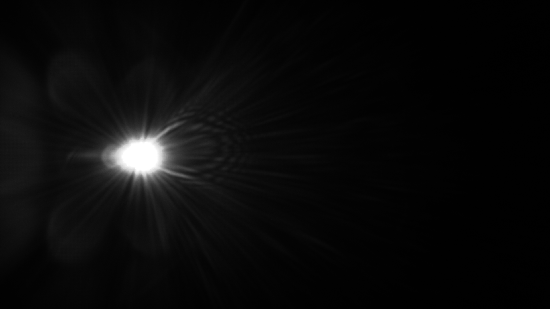
A linear monochrome stray light test image. The image was captured using a longer camera integration time and higher light level than the reference image to reveal faint stray light artifacts in the image so that we can measure their magnitude. The direct image of the source is saturated and significantly blooming, precluding meaningful measurement in that region.
Procedure for computing normalized stray light in Imatest
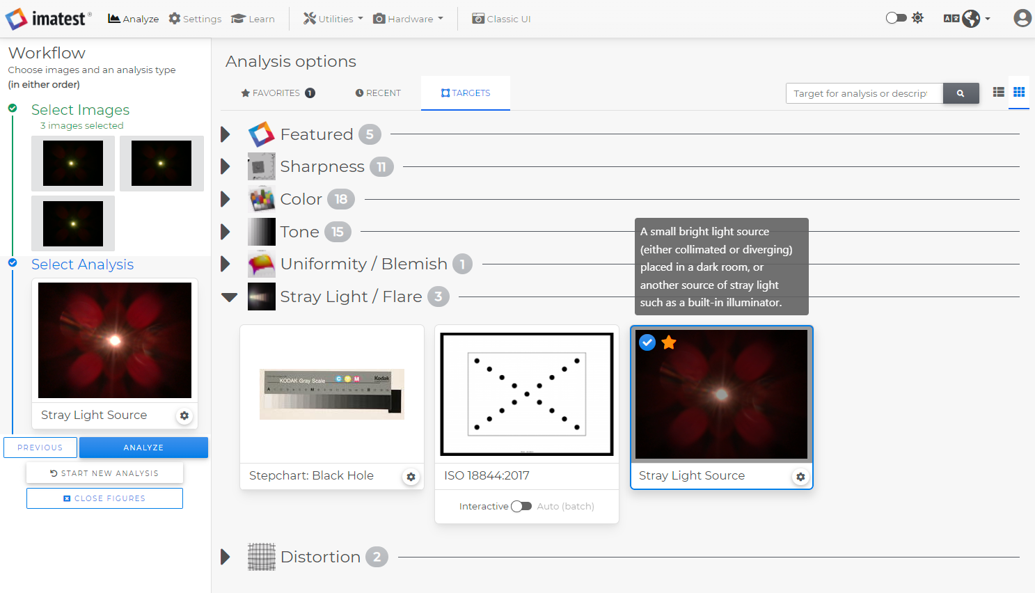
The Imatest 23.1 main window with Stray Light Source selected as the target for analysis.
- In Imatest, select the images under test and select Stray Light Source as the target for analysis.
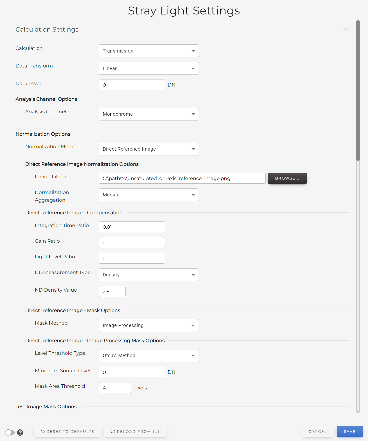
- Click the gear icon and configure the stray light settings for computing normalized stray light:
- Select Transmission (default) as the calculation type.
- Select Direct Reference Image as the normalization method.
- Enter or select the Image Filename for the reference image (the fully qualified path to the reference image file).
- Enter values for any reference image compensation settings corresponding to the techniques that were used to capture the reference image.
- Enter values for Integration Time Ratio, Gain Ratio, and Light Level Ratio if the camera integration time, gain, and light level are different between the reference image and the test images. Note: ratio values of 1 (default) are equivalent to no normalization compensation.
- If a neutral density (ND) filter was used for the reference image, select a ND Measurement Type and enter either a ND Density Value or ND Transmission Value. Note: If entering a non-zero value for ND Density Value or ND Transmission Value, keep in mind that the value for the Light Level Ratio should not include the light level lost due to the ND filter.
- For example, if a ND filter with a density of 2.5 and an exposure time of 1ms were used for the reference image, while no ND filter and an exposure time of 100ms were used for the test images, enter 2.5 as the ND Density Value and 0.01 as the Integration Time Ratio (which is the ratio of the reference image exposure time to the test image exposure time, i.e., 1/100 = 0.01).
- (Optional) Configure the Direct Reference Image – Mask Options. These determine how Imatest detects the direct image of the source in the reference image. During analysis, Imatest will derive the level from the direct image of the source within the detected/masked region. The software will then compute a compensated normalization factor based on the user-entered normalization compensation settings. See the Stray Light Masking page for more information about mask settings.
- Note: The default reference image Mask Method is Image Processing with a Level Threshold Type of Otsu’s method. These settings are meant to work for images where the direct image of the source is relatively uniform and unsaturated like the example shown above on this page.
- Note: The default reference image Normalization Aggregation is Median, which calculates the median of the masked region to derive a level.
- Note: An alternative to the Reference Image normalization method is the Level normalization method. Level requires the user to calculate a normalization factor by hand and enter the value directly. An example calculation of a value for Level is provided here.
The Direct Reference Image normalization option allow the user to have a normalization factor be automatically derived from a reference image, simplifying the process of calculation normalized stray light. If the reference image was captured using different settings (such as a different camera exposure time), additional normalization compensation options can be entered to ensure accurate normalization of the images under test.
- (Optional) Configure the Test Image Mask Options. These determine how to detect the location and size of the direct image of the source in the test images. The detected region will be masked out (set to NaN or null) or ignored in the resulting metric images. See the Stray Light Masking page for more information about mask settings.
- Enter or select an Output Directory (the fully qualified path to a folder/directory or the name of a folder in which output files will be saved).
- Note: If you enter just the name of a folder, Imatest will create a new folder with that name in the same directory as the test images, and save the outputs to that folder.
- (Optional) Configure other calculation and output settings, including metric image and video output settings, plot settings, level thresholds for pass-fail criteria, and more.
- Select Save to save the settings and close the settings window.
- Select ANALYZE on the main window to run analysis on the images. Imatest will generate normalized stray light metric images and other useful outputs based on the metric image data.
- See the Outputs Overview page for more information on the Imatest stray light outputs.
References
[1] Bruce Bouce, et al., GUERAP II Users Guide (1974).
[2] Jackson S. Knappen, “Comprehensive stray light (flare) testing: Lessons learned” in Electronic Imaging, 2023, pp 127-1 – 127-7, https://doi.org/10.2352/EI.2023.35.16.AVM-127.
