Stray light (flare) documentation pages
Introduction: Intro to stray light testing and normalized stray light | Outputs from Imatest stray light analysis | History
Background: Examples of stray light | Root Causes | Test overview | Test factors | Test Considerations | Glossary
Calculations: Metric image | Normalization methods | Light source mask methods | Summary Metrics | Analysis Channels | Saturation
Instructions: High-level Imatest analysis instructions (Master and IT) | Computing normalized stray light with Imatest | Motorized Gimbal instructions
Settings: Settings list and INI keys/values | Standards and Recommendations | Configuration file input
This page describes the technical considerations of stray light testing.
Test Assumptions
The table below describes assumptions that may be made for stray light testing, along with the associated consequences (if the assumption is not entirely true) and possible improvements to address the consequences.
| Assumption | Consequences | Possible Improvements |
|---|---|---|
| The room is black (0% reflectance, no other sources) |
|
|
| The source is appropriately bright |
|
|
| The radiance of the light is spatially constant |
|
|
| The source illuminates the front element and the mechanical surfaces that “see” the front element via a single bounce |
|
|
| The light source does not have stray light |
|
|
| The image of the source is small |
|
|
| The data are linear |
|
|
| The data are monotonic |
|
|
| All auto algorithms are turned off |
|
|
| When inside the FOV, the source is masked out |
|
|
| Stray light is radially symmetric (a single azimuth angle is good enough for testing) |
|
|
| The test equipment is not in the FOV of the DUT |
|
|
| The angle of the source relative to the DUT is known |
|
|
| All signal (outside the design path) is from stray light |
|
|
| The light source is collimated |
|
|
| The reference image compensation can be represented as single multiplicative factor |
|
|
Light Source
Collimated vs Diverging Source
From a calculation perspective, stray light may be measured with either a diverging or collimated light source. However, for repeatability between test setups, a collimated light source is recommended.
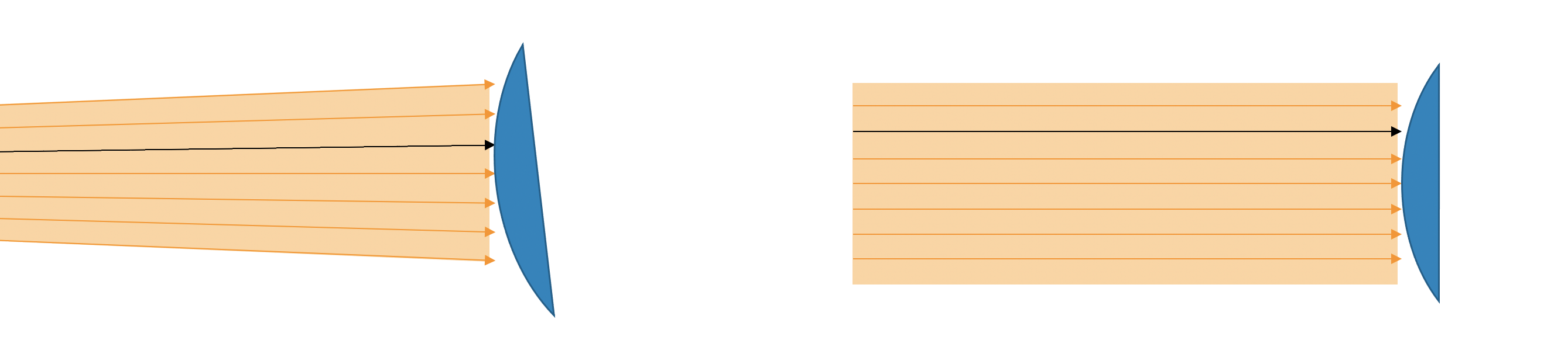
Left: Sampling with a diverging source; Right: Sampling with a collimated source. In both cases, the black bundle of rays are sampling the same angle/position combinations.
Two aspects over which stray light may be measured are the angle of rays and their intersection (translation) relative to the camera. Diverging and collimated light sources each sample in this space (rotating the camera/source builds up coverage).
Conjecture: For a small bundle of rays in one setup, there is an equivalent bundle of rays in the other. With sufficient (not defined) sampling, all bundles in one setup will be covered by one or more of the captures in the other setup. However, the other bundles in that capture may not be the same. This leads to all stray light features appearing in one will appear in the other, however, the magnitude and location (angle) may not be the same.
Collimated sources are not practical for all scenarios (e.g., testing through the windshield of a car requiring a Hubble Space Telescope-sized optic), therefore in some cases, it is recommended to test with diverging light (at the cost of measurement repeatability).
| Collimated | Diverging | |
|---|---|---|
| Advantages |
|
|
| Disadvantages |
|
|
Source Level (Brightness)
To first order, the stray light test is independent of the light level used to test (this is due to the normalization). However, in practice, due to the limited dynamic range of cameras, the light level will matter when the stray light becomes saturated or falls below the noise floor.
| Integration Time | Sample Image | Notes |
|---|---|---|
| 800 [ms] | 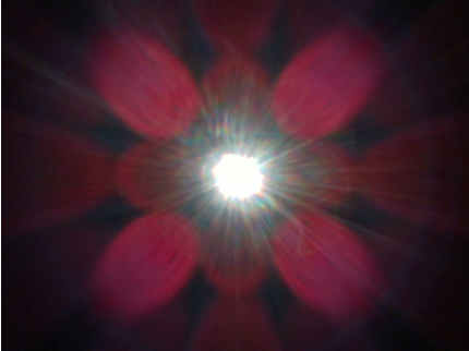 |
|
| 200 [ms] | 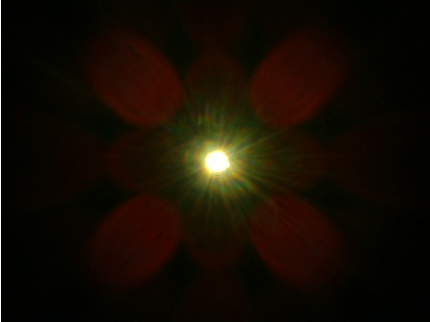 |
|
| 25 [ms] | 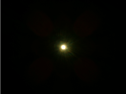 |
|
| 1 [ms] | 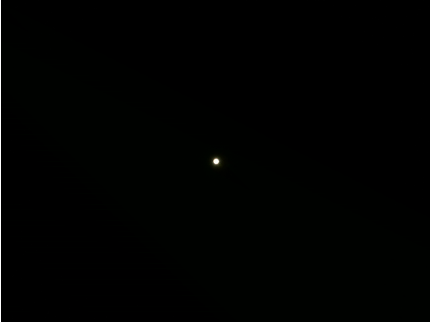 |
|
The above table shows how stray light features can be measurable at different light levels. Note: Multiple exposure levels may be needed to cover large ranges of stray light responses.
Source Extent
The source extent refers to the size of the beam at the location of the camera. The ideal source extent is slightly larger than the key surfaces of the camera. Note: that this extent will be different for every camera that is tested.
A key surface is any surface that is:
- The front optical element (e.g., lens or cover glass)
- Any surface of the camera that “directly sees” the front optical element
Examples of key surfaces include:
- Front Lens
- ND/UV filter(s)
- Baffling
- Mechanical surfaces used to hold the lens in place
- Cell phone case
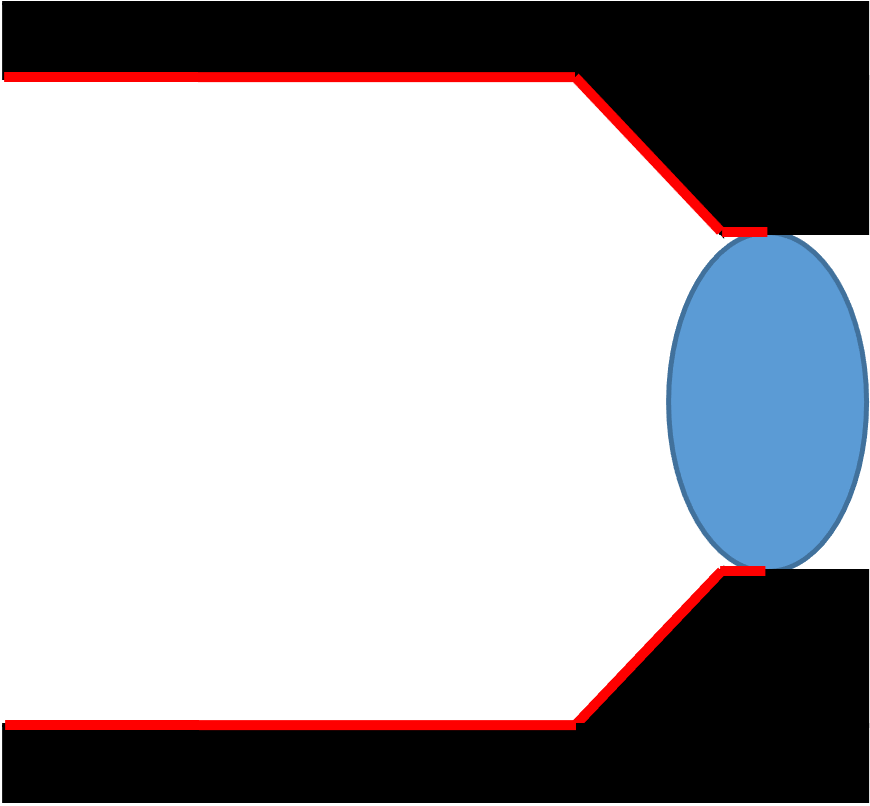
Examples of key surfaces are shown below (non-optical key surfaces are shown in red).
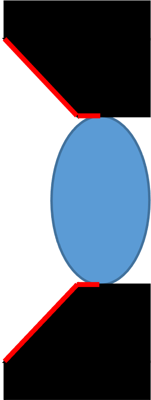 |
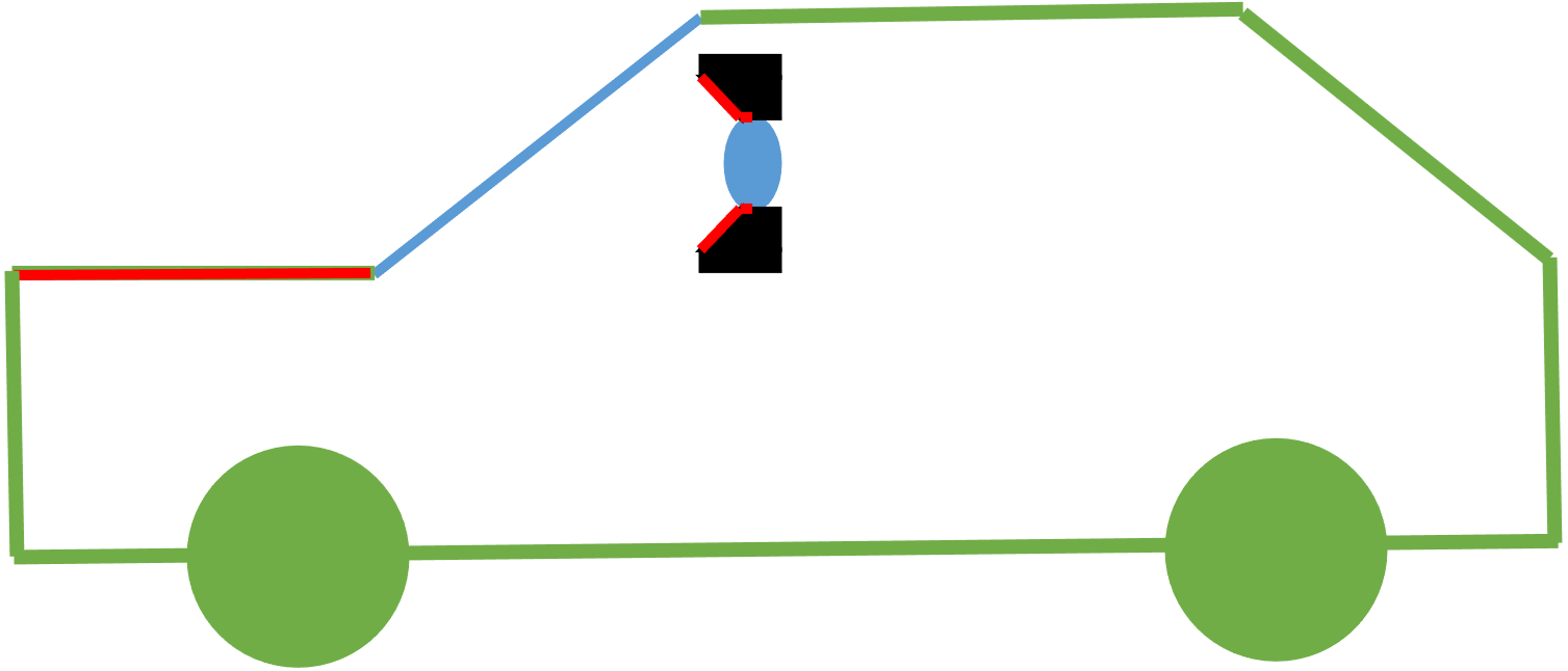 The hood of the car is a key surface when testing at the system level. |
|
| Key surfaces include the front optical element and baffling. | Key surfaces include the front optical element and the mechanical components used to hold it in place. | Key surfaces include the front optical element and lens hood. |
Note: if the source extent is much larger than the key surfaces, then there may be test hygiene problems as the “extra” light from the beam may reflect off of the camera, support equipment, and/or the room, go back out into the “scene” and create worse stray light measurements than the camera should get.
Note: that over the course of a stray light test, all of the key surfaces should be covered (at all angles). This may be done with either a single beam or by translating a smaller beam over the key surfaces.
Note: if doing “system-level” tests, surfaces outside the camera (e.g., the hood of a car and windshield are key surfaces at a system level) should also be considered to be key surfaces.
Rotation
Rotating Camera vs Rotating Source
To first order, rotating the camera and rotating the light source are functionally equivalent. However, as enumerated below, there are advantages and disadvantages for each.
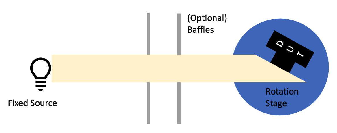
Schematic of a test setup where the camera is rotated.
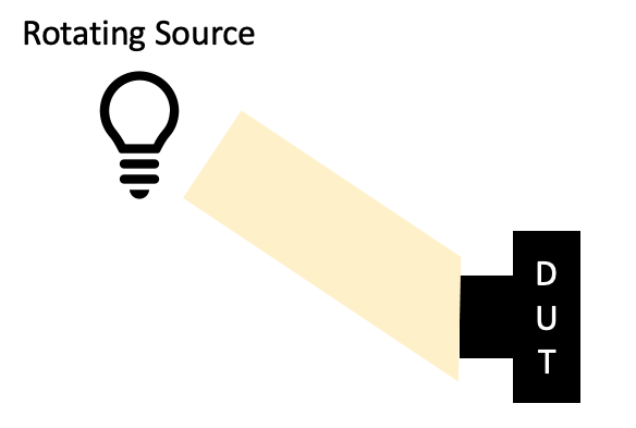
Schematic of a test setup where the light source is rotated.
| Rotating Camera | Rotating Source | |
|---|---|---|
| Advantages |
|
|
| Disadvantages |
|
|
Note the rotation point is usually defined relative to the DUT, even if the source is what is rotated.
Rotation Point
Under the assumption that the light source is collimated, large enough, and spatially uniform and the surround is infinitely black, then the rotation point does not matter. The rotation point is the point on the camera about which the camera (or source) is rotated.
The reasons for this are:
- A perfectly collimated beam will have constant irradiance with distance. This means that there is no change in light level at different test distances.
- A perfectly collimated beam will have all rays pointing in the same direction. This means that any translations will have the same intersection angle between the DUT and the beam.
- A spatially uniform beam will have the same irradiance throughout the beam. This means that any decenters (translations orthogonal to the direction of propagation of the beam) will not cause a change in light level.
- A large enough beam is required to get test coverage. Large beams may be used, however, they introduce extra light into the test setup.
- The surround being infinitely black provides a baseline level of darkness from which to measure stray light and reduces the impact of using a large beam then is strictly necessary for adding light on the measurement backgrounds.
Note that in practice, many of the assumptions are impossible to perfectly achieve with a real test setup.
The following are rotation points that may be considered:
- Point of minimum projection of key surfaces (recommended)
- Middle of the front lens element
- Entrance Pupil Position
- Exit Pupil Position
- Middle of the focal plane array (detector)
- Arbitrary point (may be useful for very wide FOVs to get the fixturing out of the way)
If the rotation point (for a collimated source) does not matter, then an optimal rotation point may be considered. The optimal rotation point is the one that minimizes the cumulative (overall measurement angles) projection of the key test surfaces onto a plane that is orthogonal to k-vector (direction of propagation) of the light source. This is illustrated in the animations below where the upper left rotation point produces the smallest projection. The cumulative projection is the minimum light source size necessary to get spatial coverage over the DUT for a rotation-only setup.
Example rotation points. In all cases, the light source is to the left side of the schematic. The current projection is the projection of the key surface(s) onto the orthogonal plane to the direction of propagation of the beam.
Minimizing the cumulative projected size allows for using smaller collimated beams. The smaller collimated light sources are easier to make than larger ones and will improve test hygiene as there is less “extra” light from the source to adversely affect measurements.
Miscellaneous
Relationship with other IQFs
Dynamic Range
Cameras with larger dynamic ranges are more susceptible to stray light as they are expected to have sensitivity over more input light levels. Larger dynamic range cameras are also better able to measure stray light as they can be sensitive to both strong (usually close to the source in digital number) and weak (further from the digital number response of the source) stray light artifacts.
(Dark) Noise
The current test assumes that any “signal” is stray light. However, dark noise is technically not stray light. Future versions of Imatest will allow for the subtraction of dark frames to separate dark noise from stray light.
Distortion
Distortion may warp the image of the source. This may require more complex light source masking methods to appropriately mask out the image of the source.
Lens Falloff
Lens falloff may affect the measured stray light values. Lens falloff is not accounted for in Imatest’s stray light analysis.
SFR/MTF
For the stray light test, blur and stray light cannot be separated (i.e., to the test, stray light and a blurry image of the light both look the same). If there is a goal of having orthogonal test metrics then the image of the light source should be in focus when testing stray light, allowing for a clearer delineation between stray light and SFR.
Optical aberrations (e.g, coma and astigmatism) with asymmetric point spread functions (PSFs) may lead to elongation of the image of the source. This may cause issues when masking out the image of the light source.
Reporting recommendations
In addition to the elements necessary for the calculation, Imatest recommends recording and reporting the following test conditions
Light Source
- Level (e.g., the irradiance at the DUT)
- Angular diameter (angular size of the direct image of the light source relative to the FOV of the DUT)
- Aperture size (minimum beam size)
- Divergence angle
- Source spectra
- Temporal stability measurements
- Any configuration the source is in
Device Under Test
- Serial number
- Integration time
- Modes (e.g., linear)
- Gain State
- Dark Noise
Test Conditions
- Source-Camera distance
- Alignment information (e.g., location of rotation point with respect to a datum on the DUT)
- Ambient (room) temperature
- Pictures of the test setup