Stray light (flare) documentation pages
Introduction: Intro to stray light testing and normalized stray light | Outputs from Imatest stray light analysis | History
Background: Examples of stray light | Root Causes | Test overview | Test factors | Test Considerations | Glossary
Calculations: Metric image | Normalization methods | Light source mask methods | Summary Metrics | Analysis Channels | Saturation
Instructions: High-level Imatest analysis instructions (Master and IT) | Computing normalized stray light with Imatest | Motorized Gimbal instructions
Settings: Settings list and INI keys/values | Standards and Recommendations | Configuration file input
Page Contents
This page provides instructions for getting started with the Imatest Motorized Gimbal. See also the stray light (flare) documentation landing page for an overview of how to set up for stray light testing.
Imatest Motorized Gimbal
The Imatest Motorized Gimbal allows for programmatic control over camera roll and yaw (or alternatively, pitch and yaw) which effectively provides control over the field angle and azimuth angle of a light source when properly set up and aligned. The Motorized Gimbal has 360-degree range for both axes and positional accuracy of 0.08 degrees. The Motorized Gimbal comes with a goniometer to help with leveling and alignment. The Imatest Motorized Gimbal is available on the Imatest Store.
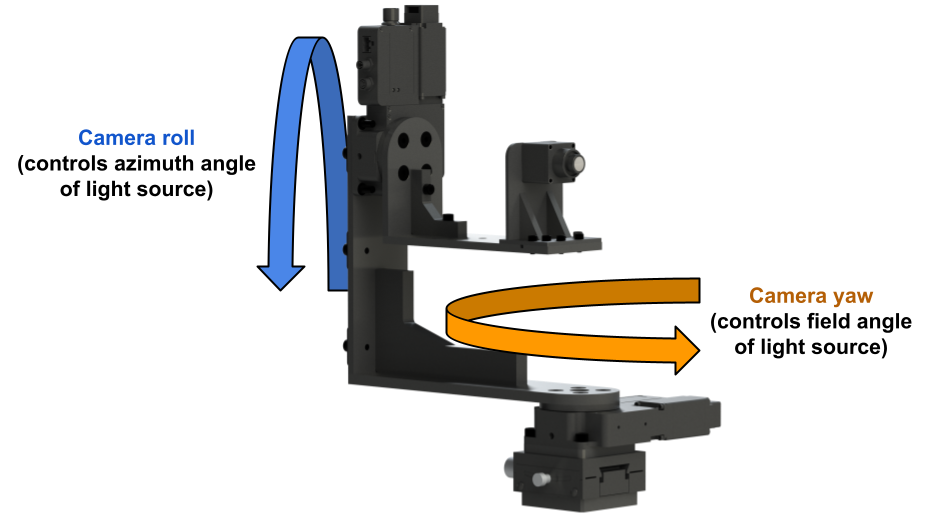
A render of the Imatest Motorized Gimbal with an automotive-grade camera (and custom camera holder) mounted in the stray light test configuration. In this configuration, the gimbal allows for control over camera roll and yaw, effectively providing control over the field angle and azimuth angle of a light source when properly set up and aligned.
Imatest Motorized Gimbal set up
The Imatest Motorized Gimbal includes two Zaber rotational stages which can be controlled over USB using a computer.
Physically set up the Motorized Gimbal by ensuring it is positioned so that no collisions or entanglement could occur if both axes are rotated 360 degrees.
Power on and connect the Motorized Gimbal to a computer using the included USB cable.
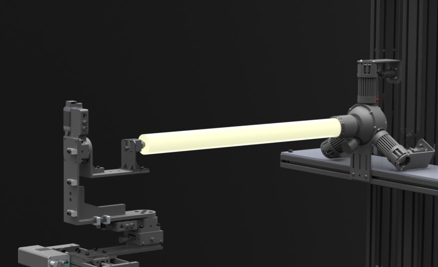
A render of the Imatest Motorized Gimbal with an automotive-grade camera (and custom camera holder) mounted in the stray light test configuration, along with a concept render of a light source. A collimated beam of light is projected from the light source and overfills the front of the camera. The camera should be mounted such that its front is located at the gimbal’s center-of-rotation. The camera should be translationally aligned within the center of the projected beam of light. To start, the camera may be rotationally aligned to be perpendicular with the light source which would correspond to an on-axis position (field angle of zero).
One option for getting started with controlling the Motorized Gimbal is to download and install the Zaber Console. The Zaber Console is an application providing the ability to command Zaber devices, adjust settings, and create simple command scripts. See the official Zaber Console documentation for additional details.
Open the Zaber Console application to set up and control the hardware for the first time. Users should update firmware as necessary and define the axis order of the two rotational stages. The axis order defines which rotational stage is which when querying for the Zaber devices within a program or script (e.g., axis index 1 = yaw and axis index 2 = roll).
Note that most Zaber devices should be “homed” (or “zeroed”) after powering on to ensure accurate absolute positioning. It is recommended to home both axes of Motorized Gimbal after a power cycle. Again, ensure that no collisions or entanglements could occur prior to homing. Homing can be performed using the Zaber Console or programmatically.
The Imatest Motorized Gimbal can be controlled programmatically with the Zaber Motion Library. The Zaber Motion Library provides an easy-to-use API (application programming interface) to control the Motorized Gimbal in a programming language of choice, such as Python, MATLAB, and/or C++. See the official Zaber Motion Library documentation for a list supported programming languages and documentation for each.
The Motorized Gimbal can be mounted to standard tripods, metric optical breadboards, and the Imatest Motorized/Modular Test Stand. When testing for stray light, the camera device under test should be mounted to the Motorized Gimbal such that its front is positioned at the Motorized Gimbal’s center-of-rotation. Currently, a user will need to design and produce their own camera holder to mount to the Motorized Gimbal. A PDF design drawing for the Motorized Gimbal in the stray light test configuration (including dimensions for mounting patterns and center-of-rotation) can be downloaded here: Imatest Motorized Gimbal design PDF
Motorized Gimbal stray light sample script
A sample script can be found in the “<Imatest IT install directory>\samples\hardware” directory, or alternatively, on Imatest’s “hardware-samples” Github repository.
The sample script is supplied in the Python programming language (version 3.8 or 3.9) which has overlapping support from Imatest IT and the Zaber Motion Control Library. Note that C++ and C# (.NET) languages also have overlapping support.
The main purpose of the sample script is to serve as an example of how one could programmatically control the Motorized Gimbal to capture images to use for stray light analysis. See also the official Zaber Motion Library documentation for basic samples and instructions on how to programmatically control Zaber devices.
Overall, the sample script demonstrates:
-
Control of the Imatest Motorized Gimbal for capturing stray light (flare) images by making use of the Zaber Motion Library
-
Generation of a Configuration file containing meta data associated with each of the captured images (image file path and corresponding light source azimuth angle and field angle)
-
(Optional, requires Imatest IT license) Stray light data analysis and results generation using the Imatest IT library with the configuration file as input
See the inline documentation within the script for more detail.
To get started with using the sample script:
- Set up a local directory to save data to and replace any necessary values within the “main()” function of the script to suit your setup and computer
- Replace the contents of the “capture_image()” function so that it calls your camera’s image capture command and saves the image to the specified file path
- Power on and connect the Imatest Motorized Gimbal to the computer
- Determine the reference azimuth angle and field angle for the Motorized Gimbal, corresponding to the absolute position where the camera is aligned with or perpendicular to the light source (field angle of zero)
- Replace the values for the “ref_az” and “ref_fa” variables (reference azimuth angle and field angle, in degrees) as needed within the “main()” function of the script
- Camera-to-source alignment is most easily done by making use of a live image feed and inspecting the position of the light source projection in the image
- Run the script. The script should:
- Capture and save a series of images at different Motorized Gimbal positions
- Create a Configuration file containing information about each position (image file path with corresponding light source azimuth angle and field angle)
- (Optional, see instructions below) Perform stray light data analysis and results generation using the Imatest IT library with the configuration file as input
Users who have an Imatest IT license can optionally perform stray light analysis within the same sample script. To get started with stray light analysis using the sample script:
- Set up and install the Imatest IT library for use in the sample script (procedure is programming language dependent).
- Uncomment the relevant block of code within the “main()” function of the script
- (Optional) Set up settings for stray light analysis in Imatest Master or by editing the Imatest INI file located in the parent directory of the script
- By default, the sample script will reference the Imatest INI file located in the parent directory of the script. This INI file defines some basic stray light analysis settings.
- If changing settings in Imatest Master, be sure to replace the contents of the referenced INI file or edit the script to reference the INI file being used by Imatest Master.
- See the Stray Light Settings page for additional info on settings and corresponding INI fields/values
- Run the script. The script should:
- Perform the same series of events described above (Motorized Gimbal movement, image capture, and configuration file generation)
- Perform stray light analysis on the captured images by referencing the configuration file as input and the Imatest
INI file for settings - The analysis will save results to the defined output directory, depending on the settings defined in the referenced Imatest INI file