Stray light (flare) documentation pages
Introduction: Intro to stray light testing and normalized stray light | Outputs from Imatest stray light analysis | History
Background: Examples of stray light | Root Causes | Test overview | Test factors | Test Considerations | Glossary
Calculations: Metric image | Normalization methods | Light source mask methods | Summary Metrics | Analysis Channels | Saturation
Instructions: High-level Imatest analysis instructions (Master and IT) | Computing normalized stray light with Imatest | Motorized Gimbal instructions
Settings: Settings list and INI keys/values | Standards and Recommendations | Configuration file input
Page Contents
This page provides a list of stray light test factors.
Introduction
Stray light measurement is a high-dimensional problem in that there are many factors that can be tested.
A comprehensive testing scheme will include coverage over all of these. In practice, some of these will use limited sampling (e.g., testing with a broadband light source) instead of sampling within that dimension.
Factors over which stray light can be measured
Source Angle
The source angle describes the angle of the bundle of rays from the light source relative to the DUT. The source angle can be described with two parameters: field angle and azimuth angle.
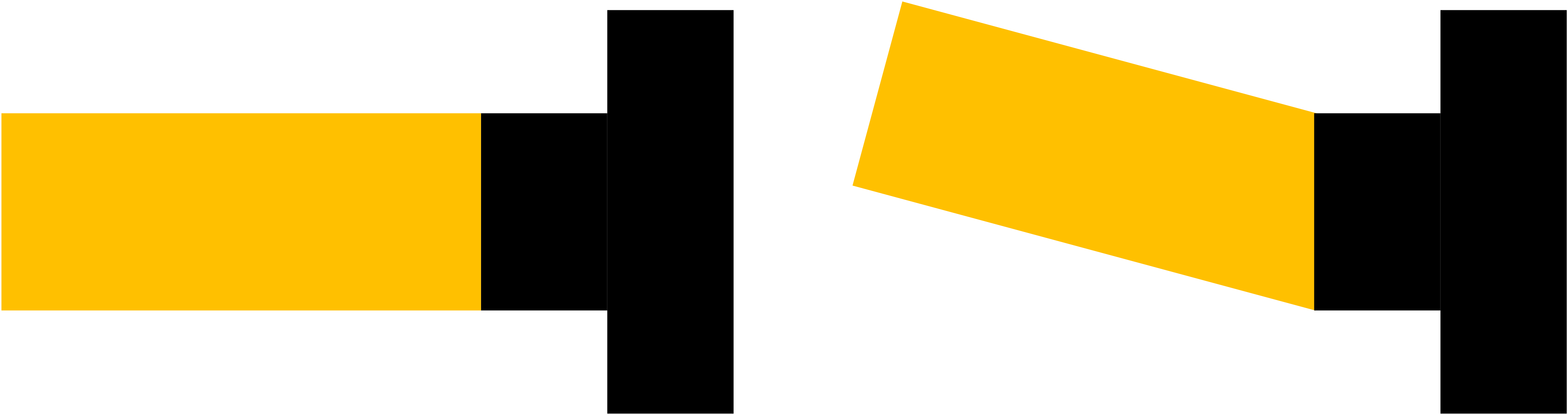
Illustration of varying the angle of the light source with respect to the camera.
Test coverage over the source angle may be obtained by:
- Fixing the light source and rotating the camera
- Fixing the camera and rotating the light source
- Using an array of light sources
- Using extended light sources
- Combinations of the above
Note: stray light may occur when the source is both inside and outside the field of view. Comprehensive testing should include samples both inside and outside the FOV.
Note: stray light may not be radially symmetric. Comprehensive testing should include sweeps of both azimuth and field angles.
Bundle Intersection with DUT
The bundle intersection with the DUT describes the spatial location where the bundle of rays intersects the DUT. The bundle intersection can be described with two parameters: x- and y- decentering values.
Note: many stray light testing setups overfill the front element, eliminating the ability to get information about these conditions.
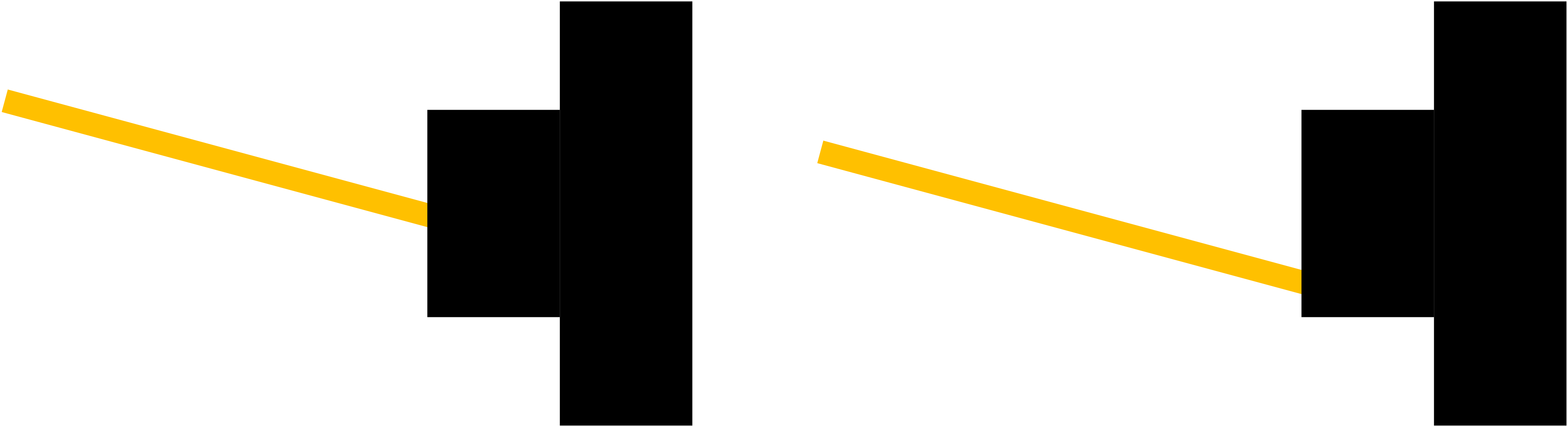
Illustration of varying the intersection location of a bundle of rays with the camera.
Test coverage over the bundle intersection may be obtained by:
- Overfilling the front element
- Translating the camera relative to the bundle of rays from the source
- Adjusting apertures of the test equipment so that the beam size varies
- Combinations of the above
Image Coordinates
The image coordinates are the location at which the stray light is sampled. It could be per-pixel or summary statistics over the image. The image coordinates can be described with two parameters: x- and y- pixel locations.
Test coverage over the image coordinates may be obtained by:
- Performing per-pixel measurements
- Computing summary statistics over regions of interest (ROIs)
- Computing summary statistics over the entire image
- Combinations of the above
Source Wavelength
Stray light may be wavelength dependent in that some wavelengths have preferentially more stray light (e.g., petal flare is predominantly red). Stray light paths involving refraction, diffraction, thin film filters, and color filter arrays are more likely to be wavelength-dependent. The wavelength dependency of the source may be described as a spectral curve or CIE illuminants (if appropriate).
Test coverage over the source wavelength may be obtained by:
- Testing with broadband illumination
- Testing with a series of spectral-band-limited sources
- Testing with narrow-spectral-band sources
- Combinations of the above
Analysis Channel(s)
The stray light response may vary from one analysis channel (e.g., red, green, blue, luminance, …) to another. An example of this is that petal flare will typically be red.
Note: Source wavelength describes stray light spectral variability in the illumination whereas analysis channels describe stray light light spectral variability in the camera response.
Test coverage over analysis channels may be obtained by:
- Analyzing each channel
- Analyzing the mean channel
- Analyzing the luminance channel. Note there are different luminance definitions that may be used
- Analyzing with a transformation of the camera’s channels (e.g., performing stray light analysis in L*a*b* space)
Polarization State
The polarization state of the light may impact the amount of stray light. This is particularly true in cases where the stray light path through the optics of the DUT involves a reflection of a surface with an angle larger than Brewster’s angle. The polarization state may be described with the three polarization components of a Stokes vector.
Note: most stray light test setups test with randomly polarized (often referred to as unpolarized light).
Test coverage over the polarization states may be obtained by:
- Testing with randomly polarized (unpolarized) light
- Testing with a series of differently polarized light (linear, spherical, elliptical)
- Combinations of the above
Source Level
The manifestation of stray light is proportional to the level of the source (e.g., luminance, irradiance, irradiance, etc.). The source level may be described with radiometric or photometric values (e.g., irradiance, radiance, lux, etc.) that are appropriate for the light source.
Note: to first order, the source level does not matter for stray light metrics that normalize out the level of the source. This first-order assumption breaks down when the source and stray light features are “far apart” relative to the dynamic range of the DUT.
Note: the light level at the camera may also be used to describe the light level of the test setup.
Test coverage over wavelength may be obtained by:
- Testing at a fixed light level (Note: some normalization methods may require that the light source be at a different level for the reference and data captures.)
- Testing at multiple light levels
- Combinations of the above
Other factors
Other factors that can affect stray light measurement are:
- DUT settings (focus, focal length, aperture)
- DUT temperature
- DUT manufacturing tolerances