by Henry Koren
1. Why care about the quality of your cameras?
The task of computer vision (CV) involves analyzing a stream of images from an imaging device. Some simple applications such as object counting may be less dependent on good camera quality. But for more advanced CV applications where there is limited control of lighting & distance, the quality of your overall vision system will depend on the quality of your camera system. This is increasingly important when an error made by the vision system could lead to a decision that impacts safety. Along with proper optimization of a CV model, ensuring that that model is fed by imagery from a high-quality camera system is critical to maximizing your system’s performance.
2. Failure modes and mitigations
You should try to test your camera in environments where your imaging system is going to be utilized, otherwise, you should expect that unforeseen system failures will occur. Performing CV tasks is significantly easier in a controlled environment. Problems with the design and construction of the vision system are exacerbated by challenging environmental conditions. Often basic camera test labs will have conditions that may be less challenging than the real world.
Below we will consider a selection of failure modes that you should be concerned about. This list should not be considered all-inclusive.
Outside working distance leads to loss of spatial acuity/MTF
A system will not have an adequate resolution if the target object is Outside of Depth of Field (DoF). For fixed focus systems, this can be mitigated by aligning the outer limit of the depth of field to the hyperfocal distance so that the device will have good enough resolution at long range, but also have reasonable focus at medium distances.
Thermal Expansion leads to loss of spatial acuity/MTF
A lens housing may have significant changes in its mechanical properties at elevation due to temperature and pressure differences. The lens of the device is not properly focused because of expansion/contraction due to temperature and pressure differences. This is particularly a concern for automotive and aerospace applications. Using a temperature chamber to ensure your device performs acceptably at the range of temperatures it will be used in is part of a comprehensive testing regimen.
Motion Blur leads to loss of spatial acuity/MTF
There is a tradeoff between capturing a brief instant in time where a small number of photons can freeze a brief moment in time but may come with low exposure (see below) or significant levels of noise, and a longer exposure meant to expose the details of dark areas at the expense of losing the detail of moving objects. The motion of the observer or the motion of objects in the scene can lead to the subject being blurred. Typically this blur is only in a single direction. Having sensors with higher quantum efficiency, and increasing the illumination of the scene can mitigate these problems.
Insufficient exposure time leads to loss of signal
Underexposure happens because the integration time of the sensor pixels is too short. Signal processing, specifically tone mapping, can be used to boost the resolvability of objects in dark areas. The boost in contrast that these routines provide will also come with additional noise, so the SNR will fall.
An increase in chief ray angle leads to loss of signal and/or crosstalk.
Pixels are most sensitive when the angle of the light, the chief ray angle, is normal to the pixel. As the angle increases, lens shading/nonuniformity can lead to fewer photons reaching the sensitive areas of pixels. This issue increases as you move from the center into the corners of your sensor. This effect can also lead to adjacent pixels having crosstalk or diffusion between each other. This is particularly a challenge for ultra-wide field of view cameras, where the lens’ image circle does not entirely cover the area of the sensor. This can be mitigated by advanced sensor technologies such as deep trench isolation, by using a curved sensor, or a sensor that has the color filter array scaled such that microlenses are adapted to the lens design.
Overexposure/saturation leads to loss of signal
Saturation means that the image is unrecoverable in that area. There is no fixing this in the post, the camera will be effectively blinded if this happens. For some scenes, like staring directly into the sun, or directly into headlights, overexposure is OK. If your ISP tries to get a good exposure of a super-bright source, the rest of the image will end up underexposed. Other bright sources may need to be properly exposed for computer vision to be successful. For example, if you need to be able to distinguish between Yellow and Orange traffic signals in an RCCB (Red Clear Clear Blue) image sensor, avoiding saturation could enable assessments based on color differences that would not otherwise be possible.
Lack of Dynamic Range
Low dynamic range cameras may try to hunt for a good exposure, this can cause a combination of under and overexposure within the same scene. This is the biggest challenge in mixed lighting scenarios such as tunnels, doors/windows to the outdoor, split shaded/sunlit, or sun within the scene. Modern sensors can use compounding to maximize the effective dynamic range of values without having a bit depth coming from your camera that is computationally expensive.
Dazzled by stray light
Bright sources such as the sun or headlights can lead to stray light in the imaging system as internal reflections between lens elements, and reflections on the camera body. This can manifest itself as ghost images that falsely appear as objects, usually radially opposite from the light source. The ghost image may obstruct the detection. This can be mitigated by anti-reflective coatings and lens hood/baffles preventing light outside the FoV from having a path into the lens.
Obstructed by moisture/mud/dirt/etc.
We experience this while driving through storms in the mountains where a mist of grime becomes adhered to the camera, degrading their performance dramatically. Or this could be spurts of blood and gore onto an endoscope’s lens. These debris, if they do not entirely occlude / obscure the target, will manifest as a reduction in dynamic range, contrast and resolution. This failure can be mitigated by hydrophobic coatings on the lens’ surface, or through active cleaning systems that spray or wipe the lens clean.
Optical Distortion
If your model is trained with an undistorted training set, you may find that the geometric compression of objects approaching the outer extents of a wide fisheye lens are not properly detected. This can be mitigated by sufficient augmentation of your training data set and by using an understanding of camera intrinsic to apply geometric distortion correction.
LED Flicker and rolling shutter can cause pulsed sources to disappear
In bright lighting conditions which include pulse width modules(PWM) LED signal lights, a limited exposure time of a particular set of pixels may lead to temporal aliasing where pulsed lights intended for human observation either disappear or blink in a manner that can obscure the computer vision system’s ability to discern the intent of the signal. Traffic lights could disappear, in cases of rolling shutters, brake lights could be mistaken for turn signals. This can be mitigated by using a sensor with LED Flicker Mitigation (LFM) technology.
3. Selected application examples
We have set up an open-source project at github.com/imatest/CV-IQ where we are demonstrating select computer vision applications and how they are impacted by image degradation. You will need Python in order to use
Won’t be able to exhaustively go through simulating every possible application failure mode in this post, but we will consider two of the most important factors in image quality: Resolution and Noise.
You may be able to extend the methodology used for these examples to fit your specific application. These examples all use OpenCV-based free/open-source tools. Your organization may have its own proprietary routines that could be studied in a similar fashion to the investigations we will do here.
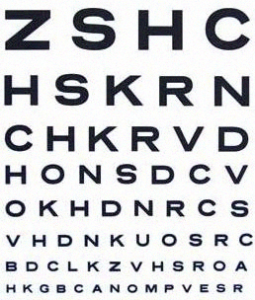
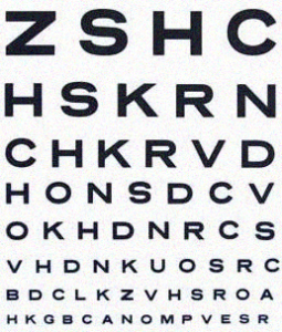
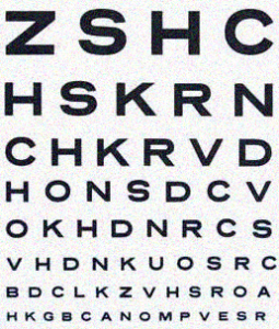
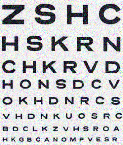
3.1. Text Recognition
This could be reading books or recognizing license plates. Having enough sensor pixels to resolve the object is necessary but not sufficient in order to carry out this task. For this study we used the Tesseract library for python to perform OCR on this image:
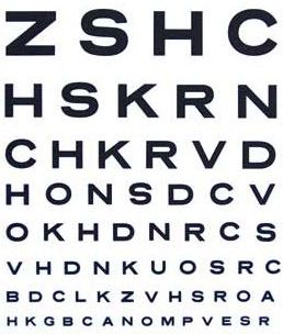
To evaluate how well the OCR performed we counted matching chunks of text using https://docs.python.org/3/library/difflib.html
3.2. QR Code Reading
We created this QR code that pointed to the Imatest web site:

We used the OpenCV QR code recognition to Identify the QR code. This results for this one are a bit less exciting to look at because of the QR code’s error protection leading to it only it producing binary results.
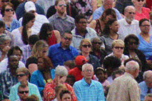
3.3. Facial recognition
We chose a reference image that includes a diverse set of complexions with the intent of reducing bias with regard to skin tones. The reference facial image was selected from a crop of Croud by Paul Sableman. Significant fringing artifacts present in this image confound the detection routines.
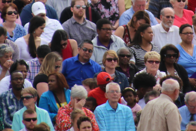
We applied the HAARCascade classifier for OpenCV to perform facial recognition and count the number of faces. Note that this method does not assess how accurately faces are identified or any false positives.
4. Simulating failure modes
We used the Wand python interface to ImageMagick library In order to perform augmentation of input imagery. This is not the most advanced of simulations, but it is able to relatively simply apply levels of blur and noise.
4.1. Sharpness
We used wand/ImageMagick’s blur filter to degrade our images. The gaussian blur function is not exactly the same as what would be produced by a real lens, but it serves as an approximation.
Here is a subset of the blur processed images:
| Info | Imatest Image | Text Image | QR Code Image | Face Image |
| Blur 1.0 | 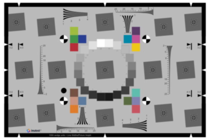 |
 |
 |
 |
| Blur 2.0 | 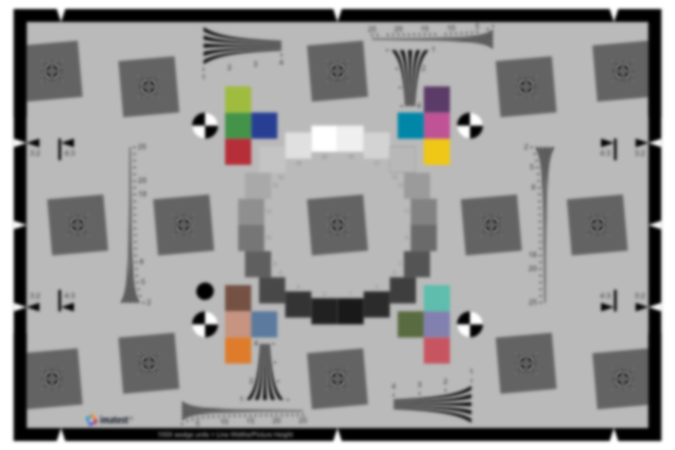 |
 |
 |
 |
| Blur 3.0 | 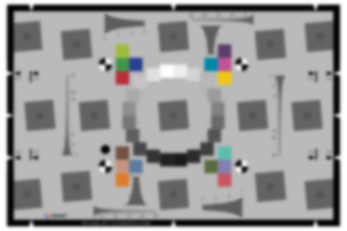 |
 |
 |
 |
| Blur 5.0 |  |
 |
 |
 |
4.2. Noise
We used wand/ImageMagick’s noise function to create gaussian noise. This may not be quite the same frequency distribution as the noise produced by a real image sensor but it serves as an approximation.
| Info | Imatest Image | Text Image | QR Code Image | Face Image |
| Noise 0.2 |  |
 |
 |
 |
| Noise 0.4 | 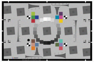 |
 |
 |
 |
| Noise 0.6 | 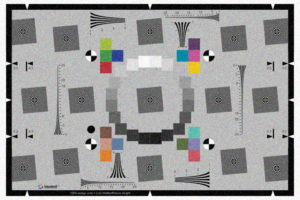 |
 |
 |
 |
| Noise 1.0 | 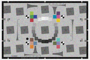 |
 |
 |
 |
These examples are just for pure blur & noise. In the simulation performed here, we combined blur and noise into two dimensions to be considered. Note that more dimensions of consideration are necessary.
5. Results
We used Imatest’s standards-based analysis routines to determine the Sharpness using MTF (Modulation Transfer Function) and Noise using SNR (Signal to Noise Ratio).
This starts with an image of an eSFR ISO test chart that is produced by the Imatest Target Generator Library

We obtained the MTF50 from a single slanted edge, and SNR from the tonal patches. We used these objective image quality metrics to replace the arbitrary noise & blur levels used by ImageMagic. This enables us to start to determine appropriate quality requirements for our camera system.
The following plots show that the noise and sharpness metrics are mostly orthogonal to each other across the simulation set. There is some effect on the sharpness measurements performed on noisier images. See Increasing the repeatability of sharpness tests for more details.
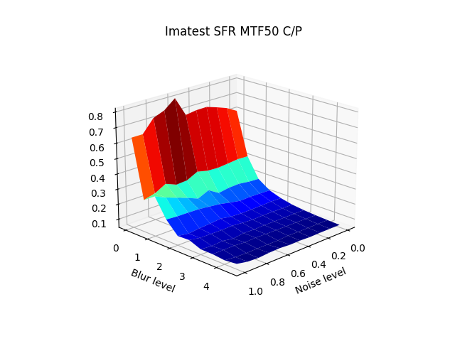
To prevent SNR from going asymptotic to over 300, if not infinity, we applied a “maximum SNR” of 50 to the noise-free image.
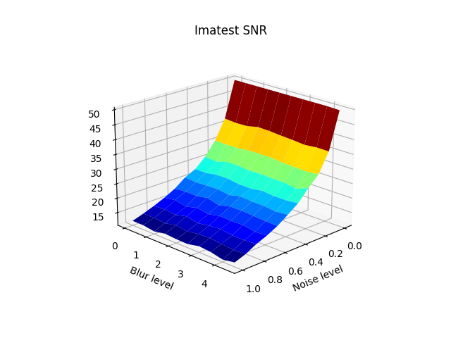
Next, we applied these objective metrics to the plots to replace the arbitrary “noise level” and “blur level” with an objective metric that can be linked to camera system performance.
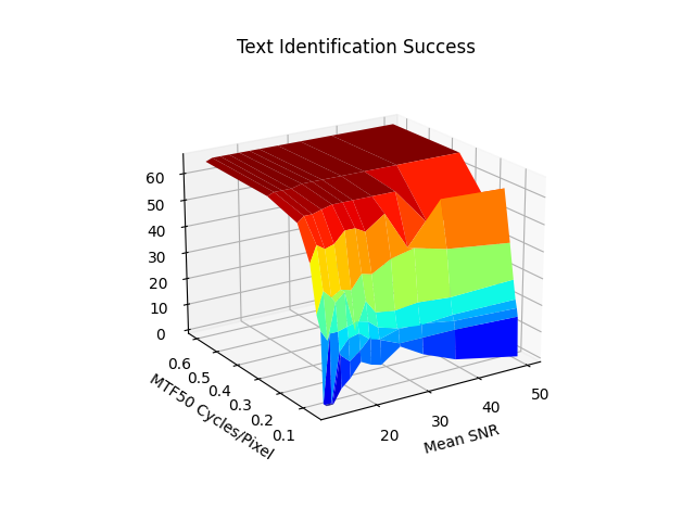
5.1. Text Recognition
We found that blur / SFR was very strongly correlated with the success of the text identification. In the medium-blur, low noise cases there were some detections that were strangely worse off without noise.
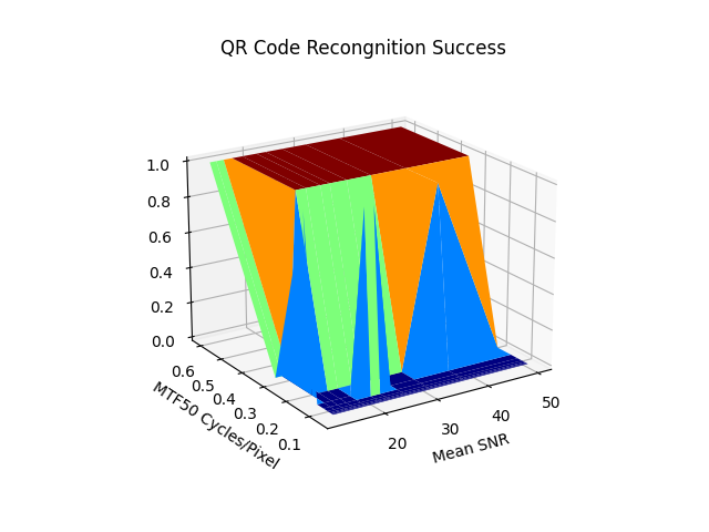
5.2. QR Code Recognition
QR Code failure started to occur consistently at SNR below 20 dB and MTF50 below 0.3 Cycles/pixel.
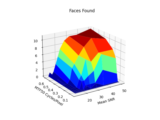
5.3. Facial Recognition
This was the most challenging task, good facial recognition required both high SNR and MTF values in order to be successful.
6. Summary
We explored how objective image quality can relate to the performance of various computer vision routines. We explored some different means for performing various computer vision tasks and we considered how the applied noise and blur simulation impacted the recognition task we were trying to perform. We can use this as a framework for continuing to improve pattern recognition systems with full consideration of how the quality of input can impact our ability to perform computer vision tasks.
Hopefully, this has been useful in helping you establish quality requirements for the cameras you use to perform CV tasks.
7. Future Work
We need to replace the crude simulations with more sophisticated models and go beyond the two dimensions of noise and blur that we considered above.
- To replace our naive blur simulation, optical simulations should be using lens design tools such as CodeV by Synopsys Inc., Ansys Zemax OpticsStudio or other lens simulations using ISETlens by SCIEN can be utilized.
- To replace our naive noise simulation, a detailed analysis of image sensor noise statistics using methods such as those established in EMVA 1288 will be embarked on. By understanding the noise of real image sensors in a diverse range of lighting and temperature conditions a model that can be used to better approximate actual sensor performance can be established.
- Other types of simulations that can facilitate reproducing the large array of camera failure modes described in section 2 should also be developed.
- It should be considered how additional image signal processing (ISP) steps, including sharpening, noise reduction and tone mapping applied before supplying images to the AI can help improve the performance of pattern recognition systems and mitigate some of the effects that lower-quality components may have on your system.
Simulations are only the beginning. The knowledge obtained during the simulation process should be used to better inform the design and manufacturing of camera systems. Once built, you should validate that your camera meets your needs by characterizing it using objective methods in a controlled environment.